
Related Manuals for Nortel Contivity 100


Summary of Contents for Nortel Contivity 100
- Page 1 Part No. 313369-A July 2001 4401 Great America Parkway Santa Clara, CA 95054 Setting Up the Contivity 100 Unit...
- Page 2 In the interest of improving internal design, operational function, and/or reliability, Nortel Networks Inc. reserves the right to make changes to the products described in this document without notice. Nortel Networks Inc. does not assume any liability that may occur due to the use or application of the product(s) or circuit layout(s) described herein.
- Page 3 European requirements only EN 55 022 statement This is to certify that the Nortel Networks Contivity 100 and Nortel Networks BayStack Instant Internet 100-S are shielded against the generation of radio interference in accordance with the application of Council Directive 89/336/ EEC, Article 4a.
- Page 4 Règlement sur le brouillage radioélectrique du ministère des Communications Cet appareil numérique (Contivity 100 ou BayStack Instant Internet 100-S) respecte les limites de bruits radioélectriques visant les appareils numériques de classe A prescrites dans le Règlement sur le brouillage radioélectrique du ministère des Communications du Canada.
- Page 5 FCC. If you experience trouble with the unit, please contact the Nortel Networks Technical Solutions Center in your area for service or repairs. Repairs should be performed only by service personnel authorized by Nortel Networks.
- Page 6 This information technology equipment is UL-Listed and C-UL-Listed for the uses described in this and accompanying documents. Warning: To avoid bodily injury from hazardous electrical shock, never open the Contivity 100 unit. There are no user-serviceable components inside. Connecting a Contivity unit to the network...
- Page 7 Cette précautions est particuliérement importante dans les régions rurales. Avertissement: L'utilisateur ne doit pas tenter de faire ces raccordements lui-même; il doit avoir recours aux services d'un électricien. Setting Up the Contivity 100 Unit...
- Page 8 Software is provided will be free from defects in materials and workmanship under normal use for a period of 90 days from the date Software is first shipped to Licensee. Nortel Networks will replace defective media at no charge if it is returned to Nortel Networks during the warranty period along with proof of the date of shipment.
- Page 9 7. Term and termination. This license is effective until terminated; however, all of the restrictions with respect to Nortel Networks’ copyright in the Software and user manuals will cease being effective at the date of expiration of the Nortel Networks copyright; those restrictions relating to use and disclosure of Nortel Networks’ confidential information shall continue in effect.
- Page 10 AGREEMENT IS THE ENTIRE AND EXCLUSIVE AGREEMENT BETWEEN NORTEL NETWORKS AND LICENSEE, WHICH SUPERSEDES ALL PRIOR ORAL AND WRITTEN AGREEMENTS AND COMMUNICATIONS BETWEEN THE PARTIES PERTAINING TO THE SUBJECT MATTER OF THIS AGREEMENT. NO DIFFERENT OR ADDITIONAL TERMS WILL BE ENFORCEABLE AGAINST NORTEL NETWORKS UNLESS NORTEL NETWORKS GIVES ITS EXPRESS WRITTEN CONSENT, INCLUDING AN EXPRESS WAIVER OF THE TERMS OF THIS AGREEMENT.
-
Page 11: Table Of Contents
Contivity 100 unit hardware installation ........ - Page 12 Configuring modem connection settings ....... . 67 Connecting a modem to the Contivity 100 unit ......70 Connecting to a Contivity 100 unit .
- Page 13 Index ............75 Setting Up the Contivity 100 Unit...
- Page 14 Contents 313369-A...
- Page 15 Figure 1 Front panel of the Contivity 100 unit ......28 Figure 2 Rear panel of the Contivity 100 unit .
- Page 16 Figures 313369-A...
- Page 17 Ethernet switch port status LEDs ....... 60 Setting Up the Contivity 100 Unit...
- Page 18 Figures 313369-A...
-
Page 19: Preface
Before using this manual, you need to do two things. First, write down the model number and serial number of your Contivity 100 unit. You will need this information if you call Nortel Networks* Technical Support. Model and serial numbers are located on the rear panel of your unit. -
Page 20: Acronyms
Preface Acronyms The following acronyms are used in this manual: Alternating Current Certification of Electrical Equipment CENELEC European Committee for Electrotechnical Standardization Command Line Interface Canadian Standards Associates Channel Service Unit Underwriter Laboratories testing to Canadian standards Decibels Audible Dual Inline Pins Demilitarized Zone Data Service Unit Full Duplex... -
Page 21: Related Publications
Branch Access management software and third-party applications (Adobe* Acrobat Reader*, Netscape Communicator*, and AniTa Terminal Emulator*). • Installing the Contivity Branch Access Management Software Version 7.20 (part number 313367-A) Provides instructions for installing the Contivity Branch Access management software. Setting Up the Contivity 100 Unit... - Page 22 — Installing the Contivity Branch Access Management Software Version 7.20 — Setting Up the Contivity 100 Unit — Setting Up the Contivity 400 Unit — Using the Contivity Branch Access Management Software Version 7.20 — Reference for the Contivity Branch Access Command Line Interface Version 7.20...
-
Page 23: How To Get Help
Preface How to get help If you purchased a service contract for your Nortel Networks product from a distributor or authorized reseller, contact the technical support staff for that distributor or reseller for assistance. If you purchased a Nortel Networks service program, contact one of the following... - Page 24 Preface 313369-A...
-
Page 25: Chapter 1 Introduction
Chapter 1 Introduction This chapter introduces your Contivity 100 unit and describes package contents, available options for your unit, and any requirements and compatibility issues. Caution: Before you install your unit, make sure that the power voltage selector switch setting matches your power voltage. For details, refer to “Setting the power voltage selector switch”... -
Page 26: Available Options
— RJ-45 crossover cable (red) for a 10BASE-T or 100BASE-T Ethernet connection Available options The Contivity 100 unit is shipped with a seven-port autosensing, autonegotiating 10/100 Ethernet switch on the front of the unit, a full-duplex/half-duplex autonegotiating 10/100 megabits per second (Mb/s) Ethernet connection on the rear of the unit, and one of the following: •... -
Page 27: Contivity 100 Unit Hardware Installation
Chapter 2 Contivity 100 unit hardware installation This chapter helps you get to know your Contivity 100 unit, and provides instructions for connecting your unit to your LAN and WAN according to the type of connection you are using, and for mounting your unit on a wall. -
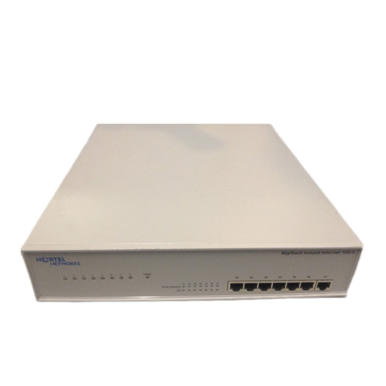
Page 28: Figure 1 Front Panel Of The Contivity 100 Unit
For details, refer to Chapter 5, “LEDs: support and diagnostic functions,” on page Figure 1 illustrates the front panel of the unit. Figure 1 Front panel of the Contivity 100 unit Contivity Power S2 S3 S6 S7 10/100 Link/Activity... -
Page 29: Interfaces
Note: If you have a triple-Ethernet unit, the third Ethernet connection (Eth3) replaces the phone jack or ISDN jack at the top of the unit. Warning: Your Contivity 100 unit contains a lithium battery. There is a danger of explosion if the battery is replaced incorrectly. The battery should be replaced only by factory authorized personnel. -
Page 30: Table 1 Ethernet Interfaces
Chapter 2 Contivity 100 unit hardware installation Table 1 describes the Ethernet interfaces available for your Contivity 100 unit. Table 1 Ethernet interfaces Interface name Interface card Type Eth1 Seven-port Ethernet switch on the front of the unit. Use Eth1 as your LAN connection. - Page 31 Chapter 2 Contivity 100 unit hardware installation Table 2 Communications interface cards (continued) Interface name Interface card Type ISDN U ISDN U interface card (integrated NT1) with one POTS connector and one RJ-45 connector. 9856ED ISDN S/T ISDN interface card (no...
-
Page 32: Power Cords
Chapter 2 Contivity 100 unit hardware installation Power cords The AC power receptacle accepts the AC power cord (supplied). For installation outside of North America, make sure that you have the proper power cord for your region. Any cord used must have a CEE-22 standard V female connector on one end and must meet the IEC 320-030 specifications. - Page 33 Chapter 2 Contivity 100 unit hardware installation Caution: Please read immediately. Inspect this power cord and determine if it provides the proper plug and is appropriately certified for use with your electrical system. Immediately discard this cord if it is inappropriate for your country’s electrical system and obtain the proper cord as required by your national electrical codes or ordinances.
-
Page 34: Setting The Power Voltage Selector Switch
Setting the power voltage selector switch The voltage of the Contivity 100 unit must match the voltage of the power source. If you set the switch to 110 and the voltage that the unit is connecting to is 200 VAC or above, you must return the unit for repair. -
Page 35: Contivity 100 Unit Hardware Installation
These steps guide you through the general process of installing your Contivity 100 unit hardware. Install your Contivity 100 unit in a ventilated area that is dust free and away from heat vents, warm air exhaust from other equipment, and direct sunlight. Avoid proximity to large electric motors or other electromagnetic equipment. - Page 36 Note: Do not apply power to the unit until you have completed the installation steps. You can mount your Contivity 100 unit on a wall or place it on a flat surface. If you choose to place the unit on a flat surface, be sure to install the unit’s rubber feet.
- Page 37 Plug the power cord into an AC wall outlet. Turn on the unit. When you turn on your Contivity 100 unit, LEDs 1 through 8 and the Power LED illuminate. LED 2 glows amber when the unit is ready for configuration.
-
Page 38: Mounting Your Contivity 100 Unit On A Wall
Chapter 2 Contivity 100 unit hardware installation Mounting your Contivity 100 unit on a wall You can mount the Contivity 100 unit on any drywall, wood, or cement wall that is at least 0.39 inches (10 mm) thick and is capable of supporting the combined weight of the unit and attached cables (approximately 11 pounds or 5 kg). -
Page 39: Attaching The Brackets To The Contivity 100 Unit
Chapter 2 Contivity 100 unit hardware installation Figure 3 Components for mounting the Contivity 100 unit on a wall 10095EA LEGEND Hole drilled in the wall Wall mounting bracket Plastic expansion lug Self-tapping drywall screw or #6 wood screw Attaching the brackets to the Contivity 100 unit Before you begin mounting the unit on a wall, you must attach the brackets to the unit. -
Page 40: Figure 4 Removing Screws From The Cover Of The Contivity 100 Unit
Chapter 2 Contivity 100 unit hardware installation Figure 4 Removing screws from the cover of the Contivity 100 unit /1 0 in k /A c ti v it y X /F n t i v i t 1 0 0... -
Page 41: Figure 5 Attaching The Mounting Bracket To The Contivity 100 Unit
100 unit on a wood wall” next. • To mount the unit on a drywall or a cement wall, continue with “Mounting the Contivity 100 unit on a drywall or cement wall” on page Setting Up the Contivity 100 Unit... -
Page 42: Mounting The Contivity 100 Unit On A Wood Wall
Chapter 2 Contivity 100 unit hardware installation Mounting the Contivity 100 unit on a wood wall To mount the Contivity 100 unit on a wood wall, you need a #6 wood screw (not included) that is long enough to penetrate the wood by at least 1/2-inch. -
Page 43: Mounting The Contivity 100 Unit On A Drywall Or Cement Wall
Mounting the Contivity 100 unit on a drywall or cement wall To mount the Contivity 100 unit on a drywall or cement wall, you need a drill and a 1/4-inch drill bit (not included). -
Page 44: Preparing A Drywall Or A Cement Wall For Mounting
Mounting the Contivity 100 unit on a drywall or cement wall You will attach one bracket at a time to the wall. To mount the Contivity 100 unit on a prepared drywall or cement wall: Align the holes in the attached bracket with the expansion lugs in the wall. - Page 45 Chapter 2 Contivity 100 unit hardware installation Insert each of the four screws through the holes in the bracket and into the expansion lugs (Figure 3 Figure Screw in the screws. Repeat steps 1–3 to attach the other mounting bracket to the wall.
- Page 46 Chapter 2 Contivity 100 unit hardware installation 313369-A...
-
Page 47: Seven-Port Autosensing Ethernet Switch Specifications
Ethernet switch in detail. Contivity unit 10/100 Ethernet switch overview The seven-port 10/100 Ethernet switch on the front of the Contivity 100 unit has seven 10/100 autosensing ports. Each port automatically senses and adapts to the... -
Page 48: Ethernet Switch Features
Chapter 3 Seven-port autosensing Ethernet switch specifications Ethernet switch features The Contivity 100 unit seven-port 10/100 Ethernet switch offers: • Seven RJ-45 10BASE-T/100BASE-T autosensing Ethernet ports with autonegotiation capability. The eighth port is used internally to connect to the internal Ethernet controller. -
Page 49: Mdi/Mdi-X Autosensing Capability
When you plug an Ethernet cable into a port, the Ethernet switch autosenses whether the cable is MDI (uplink or crossover) or MDI-X (normal or straight-through). This feature enables you to connect the Contivity 100 unit to another Ethernet connection regardless of whether you are using a straight-through cable or a crossover cable. - Page 50 Chapter 3 Seven-port autosensing Ethernet switch specifications 313369-A...
-
Page 51: Configuration Switch Settings
Configure 9871EA The switches have two possible positions: on and off. For the Contivity 100 unit, the off position is up and the on position is down. Use a small instrument with a fine point, such as the tip of a pen or a straightened paper clip, to move the switches to the proper position. -
Page 52: Switch Settings For Normal Operation
Chapter 4 Configuration switch settings Switch settings for normal operation Leave all switches off for normal operation, as shown in Table Table 5 Switch settings for normal operation • • • • • • • • Switch settings for the AUX port speed When you set all switches to off for normal operation, the unit’s AUX port speed is set to 115200 baud. -
Page 53: Switch Settings For Special Configurations
Chapter 4 Configuration switch settings Switch settings for special configurations During the power-up sequence, your Contivity 100 unit checks the settings of the switches. You can use the switches on your unit to: • Reset the passwords (Table 7), which is useful if you forget the unit’s password. -
Page 54: Table 9 Switch Settings To Disable Switch Settings For Resetting The Passwords And User-Defined Configurations
Chapter 4 Configuration switch settings Table 9 shows the switch settings to disable the switch settings for resetting the passwords and user-defined configurations Table 9 Switch settings to disable switch settings for resetting the passwords and user-defined configurations • • •... -
Page 55: Resetting Your Contivity 100 Unit
Chapter 4 Configuration switch settings Resetting your Contivity 100 unit Before you reset your Contivity 100 unit, be sure to back up the configuration so that you can easily restore it. For details, refer to Using the Contivity Branch Access Management Software Version 7.20. - Page 56 Chapter 4 Configuration switch settings • If you reset the passwords and user-defined configurations (Table 8) reset the unit to factory defaults (Table 10), LED 2 glows amber when the unit is ready for configuration. Continue with step 8. Note: You may have to wait several minutes for LED 2 to glow amber. Configure your unit.
-
Page 57: Leds: Support And Diagnostic Functions
Interpreting Contivity 100 unit LEDs The front panel of the Contivity 100 unit has two sets of LEDs, the eight LEDs on the left indicate failures and operational status of the unit. The Power LED is always lit when your unit is turned on. -
Page 58: Leds 1 Through 8 And Power Led At Power-Up Sequence
If a failure occurs during the power-up sequence, the Power LED glows amber, and one or more of LEDs 1 through 8 glow red. This sequence indicates a hardware problem. Call the Nortel Networks Technical Solutions Center (page 23) for assistance. -
Page 59: Leds 1 Through 8 And The Power Led During Operation
Note: The “indicated interface” is the interface associated with the LED’s number. This information is available in the main dialog box of the Setup program. For more information, refer to Using the Contivity Branch Access Management Software Version 7.20. Setting Up the Contivity 100 Unit... -
Page 60: Using The Seven-Port Autosensing Ethernet Switch Leds For Troubleshooting
Chapter 5 LEDs: support and diagnostic functions Using the seven-port autosensing Ethernet switch LEDs for troubleshooting The seven-port autosensing Ethernet switch has two LEDs for each port on the Ethernet switch. The top row of these LEDs displays speed, link, and activity. The bottom row of LEDs displays whether the unit is operating in full- or half-duplex mode. -
Page 61: Out-Of-Band Management Support
Chapter 6 Out-of-band management support This chapter describes how to set up your Contivity 100 unit for out-of-band management. This feature enables you to configure your unit without installing the unit on a network or loading the Contivity Branch Access management software. -
Page 62: Configuring The Contivity 100 Unit Through A Direct Connection
To configure the Contivity 100 unit through a direct connection to a dumb or smart terminal using the out-of-band management feature, you must: Use the Configuration switches on the back of the Contivity 100 unit to set the unit’s AUX port connection speed (115200 baud or 9600 baud) to match the terminal’s connection speed. -
Page 63: Configuring Terminal Emulation Software For A Direct Connection
Chapter 6 Out-of-band management support To connect the Contivity 100 unit to a terminal: Plug one end of the null modem cable into the AUX port on the rear of the unit. Plug the other end of the cable into the serial port on the terminal. -
Page 64: Figure 9 Hyperterminal Connection Description Dialog Box
Chapter 6 Out-of-band management support Figure 9 HyperTerminal Connection Description dialog box In the Name box, enter a name for the connection. In the Icon area, select an icon for the connection. Click OK. The Connect To dialog box opens (Figure 10). -
Page 65: Figure 11 Hyperterminal Com1 Properties Dialog Box
If you enter an incorrect password, the message “Incorrect Login” is displayed and you are prompted to enter a correct password. You are given two more chances before the Contivity 100 unit ends the session and disconnects you. When you successfully log on, the command prompt is displayed (Figure 12) you can begin using CLI commands to configure the unit. -
Page 66: Configuring The Contivity 100 Unit Through A Dial-Up Connection
To configure the Contivity 100 unit through a dial-up connection using the out-of-band management feature, you must: Use the Configuration switches on the back of the Contivity 100 unit to set the unit’s AUX port connection speed to 9600 baud. For details, refer to “Switch... -
Page 67: Configuring Modem Connection Settings
The Connection Description dialog box opens (Figure 13). Figure 13 HyperTerminal Connection Description dialog box In the Name box, enter a name for the connection. In the Icon area, select an icon for the connection. Click OK. Setting Up the Contivity 100 Unit... -
Page 68: Figure 14 Hyperterminal Connect To Dialog Box
Chapter 6 Out-of-band management support The Connect To dialog box opens (Figure 14). Figure 14 HyperTerminal Connect To dialog box From the Connect using list, select the PC’s COM port that is connected to the modem (in this example, COM1), and then click OK. The COM1 Properties dialog box opens (Figure 15). -
Page 69: Figure 15 Hyperterminal Com1 Properties Dialog Box
This command instructs the modem to answer on the first ring and saves the settings to the modem. Some modems respond with “OK” or a similar message when the settings are saved to the modem. Disconnect the modem from the PC. Setting Up the Contivity 100 Unit... -
Page 70: Connecting A Modem To The Contivity 100 Unit
Chapter 6 Out-of-band management support Connecting a modem to the Contivity 100 unit Before you connect the modem to the Contivity 100 unit, you must turn off the unit. Note: Before you continue with this procedure, be sure that you have properly configured the modem connection settings. -
Page 71: Technical Specifications
Technical specifications This appendix describes the physical and environmental specifications for your Contivity 100 unit. Physical specifications The Contivity 100 unit is 12 inches wide by 14.39 inches deep by 2.64 inches high and weighs 8.8 pounds. Electrical specifications •... -
Page 72: Environmental Specifications
Appendix A Technical specifications Environmental specifications The operating and nonoperating environment for the Contivity 100 unit is as follows: • Operating temperature: 0° to 40° C maximum • Nonoperating temperature: -25° to 70° C maximum • Operating humidity: — 8% minimum to 80% maximum —... -
Page 73: Adapter Cable Pinout Diagrams
Remote access adapter cables If you want to connect a PC or dial-up modem directly to your Contivity 100 unit to configure the unit using CLI commands (out-of-band management), you must provide the connection cable. These are standard cables. You can have a cable made according to the pinout diagrams in this appendix or you can purchase the cable from a computer supply store. -
Page 74: Modem Adapter Cable
74 Appendix B Adapter cable pinout diagrams Figure 16 Null modem adapter cable pinout diagram DB-9 Connector DB-9 Connector (Female) (Female) 9959EA Modem adapter cable Figure 17 shows the pinout settings for a modem adapter cable. This serial cable must have a DB-9 female connector and a DB-25 male connector. Use a modem cable to connect a dial-up modem to the unit’s AUX port for out-of-band management. -
Page 75: Index
61, 73 PC-to-PC file transfer 61, 73 pinout diagrams 73 red 26 Eth1 remote access 73 Ethernet switch 30, 37 RJ-11 connection 25 LAN connection 30, 37 RJ-45 connection 26 straight-through 49 Setting Up the Contivity 100 Unit... - Page 76 Index Eth2 built in 28 LEDs DMZ connection 30, 37 about 57 Eth3 29 activity 59 external modem connection 37 after power-up sequence 59 WAN connection 30 Ethernet switch 60 Ethernet connection full-duplex (FDX) 48, 60 100BASE-T 26 half-duplex (HDX) 48, 60 10BASE-T 26 interpreting 57 Link/Activity 48, 60...
- Page 77 53 ProComm Plus 61 product support 23 publications voltage 34 hard copy 22 related 21 wall mounting 38 RJ-11 connector 30 RJ-45 connector 31 smart terminal 61 support, Nortel Networks 23 Setting Up the Contivity 100 Unit...
- Page 78 Index 313369-A...
Need help?
Do you have a question about the Contivity 100 and is the answer not in the manual?
Questions and answers