Table of Contents
Advertisement
Quick Links
Advertisement
Table of Contents

Related Manuals for PerkinElmer Spotlight 200

Summary of Contents for PerkinElmer Spotlight 200
- Page 1 MOLECULAR SPECTROSCOPY Spotlight 200 User’s Guide...
- Page 2 The information contained in this document is subject to change without notice. Except as specifically set forth in its terms and conditions of sale, PerkinElmer makes no warranty of any kind with regard to this document, including, but not limited to, the implied warranties of merchantability and fitness for a particular purpose.
-
Page 3: Table Of Contents
Infrared Optics ..................37 Spotlight System Requirements .................39 Hardware Requirements ................39 Software Requirements ................39 Getting Ready to Use the Spotlight 200 ..........41 Before Using the Spotlight 200 ................42 Cooling the MCT Detector .................43 Setting up the Spotlight 200 ................46 Focusing the Microscope ................46 Fitting an Attenuator to the Spectrometer ...........48... - Page 4 4 . Spotlight 200 User’s Guide Fibers ....................... 63 Fibrous Solids ................... 63 Coatings on Substrates ................64 Liquids ..................... 64 Techniques for Collecting Spectra ............65 Techniques for Collecting Spectra ..............66 Using the Compression Cell ............... 66 Using a Hot/Cold Stage ................67 Collecting the Spectrum of a Thick Sample ..........
- Page 5 Spotlight 200 User’s Guide . 5 Connecting the Microscope to the Spectrometer ........122 Connections to the Stage Controller ............123 Appendices ..................... 127 Appendix 1: Decontamination and Cleaning ............. 128 Appendix 2: WEEE Instructions for PerkinElmer Products ........129 Index ......................130...
- Page 6 6 . Spotlight 200 User’s Guide...
-
Page 7: Introduction
Introduction... -
Page 8: About This Manual
Spotlight 200: Getting Ready to Use the Spotlight 200 • gives you information on how to set up your Spotlight 200 at the beginning of the day's work, to make sure that it is working properly. Preparing Samples • describes techniques for preparing many types of microscopic samples. -
Page 9: Conventions Used
ALT+F. All eight digit numbers are PerkinElmer part numbers unless stated otherwise. “Spectrometer” refers to the Frontier IR System, Spectrum 100 Series, Spectrum 400 Series or Spectrum One spectrometer supplied with your Spotlight 200. - Page 10 10 . Spotlight 200 User’s Guide We use the term CAUTION to inform you about situations that could result in serious damage to the instrument or other equipment. Details about CAUTION these circumstances are in a box like this one.
- Page 11 Introduction . 11 We use the term WARNING to inform you about situations that could result in personal injury to yourself or other persons. Details about these circumstances are in a box like this one. WARNING Warning (Warnung) Bedeutet, daß es bei Nichtbeachten der genannten Anweisung zu einer Verletzung des Benutzers kommen kann.
-
Page 12: Definitions
Connecting the PC to the Local Area Network The PC provided is connected point-to-point to the Spotlight 200. If you wish to connect the PC to your local area network to enable transfer of data, we recommend that you contact... -
Page 13: Warnings And Safety Information
Warnings and Safety Information... -
Page 14: The Spotlight 200
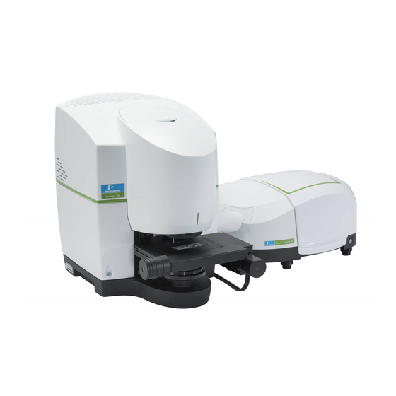
14 . Spotlight 200 User’s Guide The Spotlight 200 The Spotlight 200 consists of a microscope, spectrometer, PC, stage controller and joystick. Figure 1 Spotlight 200 – microscope and Frontier IR System Figure 2 Spotlight 200 – microscope and Spectrum Two System... -
Page 15: Summary
Spotlight 200. DO make sure that all parts of the Spotlight 200 are properly connected to the electrical • supply; in particular, make sure that the ground (earth) wires are securely connected. -
Page 16: General Operating Conditions
Frontier IR Systems, Spectrum 400 Series and Spectrum 100 Series spectrometers. The microscope and stage controller have been designed and tested in accordance with PerkinElmer specifications and in accordance with the safety requirements of the International Electrotechnical Commission (IEC). The microscope and stage controller conform to IEC publication 61010−1 (“Safety requirements for electrical equipment for... -
Page 17: Electrical Safety
Disconnect the microscope and stage controller from all voltage sources before they are opened for any adjustment, replacement, maintenance or repair. Any adjustment, replacement, maintenance or repair must be performed by a PerkinElmer Service Engineer. The microscope and stage controller must only be connected to equipment meeting the requirements of IEC 61010-1 (Safety requirements for electrical equipment for measurement, control and laboratory use –... -
Page 18: Location And Ventilation
18 . Spotlight 200 User’s Guide Location and Ventilation The Spotlight 200 is installed by a PerkinElmer Service Engineer, who will be able to advise on the positioning of the system. To allow for adequate cooling, the system should not be sited near to room heating equipment, for example, central-heating radiators. -
Page 19: Warning Labels
Warnings and Safety Information . 19 Warning Labels When this label is attached to an instrument it means “Caution, risk of danger”. Refer to the manual to find out the nature of the potential hazard and any actions which have to be taken. Microscope Safety Labels The following safety labels are fixed to the microscope. -
Page 20: Stage Controller Safety Labels
20 . Spotlight 200 User’s Guide Figure 4 Inside Dewar lid – MCT detector versions only NOTE: See Cooling the MCT Detector on page 43 for information on how to fill the Dewar. Stage Controller Safety Labels Warning Disconnect supply... -
Page 21: Warning Signs On The Microscope
Warnings and Safety Information . 21 Warning Signs on the Microscope Caution, risk of electric shock. Caution, risk of danger. Refer to accompanying documents to find out the nature of the potential hazard and any actions which have to be taken. -
Page 22: Mechanical Safety
22 . Spotlight 200 User’s Guide Mechanical Safety When you are using a motorized stage, do not place your fingers between the moving and fixed parts of the stage. The motors driving the stage from side to side, front to back, or up and down are powerful and do not stall easily. -
Page 23: Lifting The Spotlight 200
Do not attempt to lift it by the stage, cassegrain assembly or other attachments. The spectrometer weighs approximately 34 kg unpacked and has a lifting recess on either side. Do not move the Spotlight 200 after it has been installed without consulting your local PerkinElmer service department. -
Page 24: Emc Compliance
24 . Spotlight 200 User’s Guide EMC Compliance EC directive The Spotlight 200 has been designed and tested to meet the requirements of the EMC Directive 2004/108/EC. The Spotlight 200 complies with the EMC standard EN61326, (EMC standard for electrical equipment for measurement, control and laboratory use) and EN55011 (ISM) class A (rf emissions). -
Page 25: System Requirements
The line supply must be within 10% of the nominal voltage. For example, 230 V ± 10%. If possible, do not connect any parts of the Spotlight 200 to circuits that have heavy duty equipment, such as large motors, connected. - Page 26 • Make sure that the bench top is free from vibrations or mechanical shocks, and is flat and level. Do not place the Spotlight 200 near to room heating equipment, for example central • heating radiators. Leave a gap of at least 15 cm (6 inches) to the sides of the microscope and stage controller box to permit an adequate flow of cooling air.
-
Page 27: Safety Specifications
Warnings and Safety Information . 27 Safety Specifications Microscope Power supply 100–230 V ± 10%, 50/60 Hz ± 10% Primary fuse 2.0 A T (time-lag), 250 V Weight 32 kg without the motorized stage Stage Controller Power supply 100–240 V ± 10% , 50/60 Hz ± 10% Primary fuse 1.6 A T (time-lag), 250 V The control box is not designed for use with all... - Page 28 28 . Spotlight 200 User’s Guide...
-
Page 29: Overview Of The Spotlight 200
Overview of the Spotlight 200... -
Page 30: A Guided Tour Of The Spotlight 200
The image of your sample is displayed in the Monitor Visible window on your PC monitor. Spectrum software enables you to control the operation of your Spotlight 200, and collect IR spectra from the sample. -
Page 31: Connections
Overview of the Spotlight 200 . 31 Connections Figure 6 to Figure 9 show the input and output connections on the microscope and stage controller. Connections to stage controller Figure 6 Connections to Stage Controller SP1 – connects to spectrometer... - Page 32 32 . Spotlight 200 User’s Guide Connects PC to automatic ATR (if Stage Z – present), USB Connects to Stage controller Z motor Purge gas connection Connects to Stage controller Connects to PC 15-way D type RS232, 9-way D type...
-
Page 33: Operation
Overview of the Spotlight 200 . 33 Operation Spectrum software enables you to mark points of interest on the sample. You can collect individual spectra (either at the current aperture position or at positions you have marked) with or without an ATR objective. You can also collect spectra at regularly spaced intervals along a line or within a marked area. -
Page 34: The Optical System
Spotlight 200 enables you to select between transmittance and reflectance operation. This section describes what happens within the optical system when the system changes from visible light to infrared mode in transmittance and reflectance operation. - Page 35 Figure 10 Path of the Visible Beam for Viewing a Sample in Transmittance NOTE: Figure 10, above, illustrates a Spotlight 200 with an MCT detector. Other detector types may look different, but the optical arrangement is the same in all cases.
- Page 36 Figure 11 Path of the Visible Beam for Viewing a Sample in Reflectance NOTE: Figure 11, above, illustrates a Spotlight 200 with an MCT detector. Other detector types may look different, but the optical arrangement is the same in all cases.
-
Page 37: Infrared Optics
Figure 12 Path of the Infrared Beam for Collecting an Image in Transmittance NOTE: Figure 12, above, illustrates a Spotlight 200 with an MCT detector. Other detector types may look different, but the optical arrangement is the same in all cases. - Page 38 Figure 13 Path of the Infrared Beam for Collecting IR Spectra in Reflectance NOTE: Figure 13, above, illustrates a Spotlight 200 with an MCT detector. Other detector types may look different, but the optical arrangement is the same in all cases.
-
Page 39: Spotlight System Requirements
Overview of the Spotlight 200 . 39 Spotlight System Requirements Spotlight 200 requires additional cards to be installed in the PC. If you encounter a problem with the PC, contact a PerkinElmer Service Engineer. Do not attempt to remove the cards from the PC or install the software on another PC. - Page 40 40 . Spotlight 200 User’s Guide...
-
Page 41: Getting Ready To Use The Spotlight 200
Getting Ready to Use the Spotlight 200... -
Page 42: Before Using The Spotlight 200
• Set up the microscope; • Focus the microscope. We recommend that you use these procedures at the beginning of the day's work, or any time the Spotlight 200 has not been in use or has been used by others. -
Page 43: Cooling The Mct Detector
Use the following procedure to cool the MCT detector. NOTE: If your Spotlight 200 is fitted with a DTGS or InGaAs detector, cooling with liquid nitrogen is not required. The extremely low temperature of liquid nitrogen can burn skin and eyes. - Page 44 44 . Spotlight 200 User’s Guide 1. Open the flap covering the dewar. 2. Remove the dewar cap. 3. Place the small funnel supplied with the microscope in the opening in the detector dewar (Figure 14). Figure 14 The Dewar Opening with the Funnel Inserted Stand where you can see the inside of the funnel as you pour the nitrogen in, but without positioning your head over the funnel itself.
- Page 45 Getting Ready to Use the Spotlight 200 . 45 7. Remove the funnel and wait two minutes. The liquid nitrogen settles down and bubbling slows. 8. When the nitrogen stops bubbling, refit the detector cap. The filled dewar cools the MCT to the correct operating temperature for several hours.
-
Page 46: Setting Up The Spotlight 200
The blue LED light at the front comes on. 3. Switch on the stage controller. The green LED light at the front comes on. 4. At your PC, click Start and then select Spectrum in the PerkinElmer Applications group under All Programs. Spectrum software starts. - Page 47 Camera View toolbar. The image of the sample is focused. NOTE: If your Spotlight 200 system is supplied with a Frontier or Spectrum 400 FT-IR/FT-NIR dual-range spectrometer and this has been setup to work in the near infrared, you may find that there is a red tint to the image when viewed in the visible range.
-
Page 48: Fitting An Attenuator To The Spectrometer
48 . Spotlight 200 User’s Guide NOTE: If your Spotlight 200 system is supplied with a Frontier or Spectrum 400 FT-IR/FT-NIR dual-range spectrometer and you are using a large aperture in the near infrared, the software may report an overload error when monitoring an IR function or collecting data. - Page 49 −1 to 4000 cm NOTE: To work in the near infrared range of the spectrum, the Spotlight 200 must be attached to a dedicated NIR spectrometer or a dual-range spectrometer which has been set up to operate in the near infrared range.
- Page 50 50 . Spotlight 200 User’s Guide 1. Place the thin, flat, sample onto a window (or across an aperture) and use the joystick to bring the sample into visible focus. If necessary, use the Auto-Focus option to focus the image.
-
Page 51: Preparing Samples
Preparing Samples... -
Page 52: Preparing Samples
52 . Spotlight 200 User’s Guide Preparing Samples The Spotlight 200 enables you to examine the sample in the Camera View window to choose the area where you want to collect images or spectra. To make sure that you collect good quality spectra, it is important that you prepare samples properly. -
Page 53: Tools For Sample Preparation
Preparing Samples . 53 Tools for Sample Preparation This section lists the tools you need for preparing samples: Tools provided with the Spotlight 200; • Tools in the microsampling toolkit; • • Materials to have available; • Specialized accessories you may want to purchase. - Page 54 54 . Spotlight 200 User’s Guide Figure 16 Some of the Tools in the Microsampling Toolkit The following tools are provided in the Microsampling toolkit (see Figure 16). Tool Steel tweezers Picking up extremely small objects Roller knife Cutting (knife end) and flattening (roller end)
-
Page 55: Other Useful Tools
1.5 mm microdisk; fits in 13 mm disk holder to support 01861043 very small samples The following items are available from your local PerkinElmer sales office or agent: Specialized Accessories The following accessories are extremely useful in preparing certain types of samples (as... -
Page 56: Items To Have Available
56 . Spotlight 200 User’s Guide Items to Have Available In addition to the items provided with the Spotlight 200, we recommend that you have the following available: Tape with adhesive on both sides (“double-sided tape”) for holding long or large •... -
Page 57: Common Window Materials
Preparing Samples . 57 Common Window Materials Both liquid and solid samples are often mounted on salt windows. Very thin windows, 1 to 2 mm thick, give the best spectra. The following materials are commonly used in windows: KBr: Potassium bromide is inexpensive, and it transmits infrared radiation to below •... -
Page 58: Techniques For Preparing Samples For Transmittance Measurements
58 . Spotlight 200 User’s Guide Techniques for Preparing Samples for Transmittance Measurements This section describes some useful techniques for preparing various types of samples. Flattening Solids Flattening samples by pressing or squeezing often enables you to make thick samples thin enough to give good infrared spectra. -
Page 59: Slicing Samples From Solids
Preparing Samples . 59 Compressing between infrared transmitting windows Pressing two windows together, with the sample between them, compresses the sample. This also provides optical contact between the windows and the sample, reducing surface scattering. Windows made of NaCl or KBr are relatively soft. If your sample is hard, or if it is wet, use or ZnSe. -
Page 60: Polymers
60 . Spotlight 200 User’s Guide 2. Run a razor blade or the roller knife along the edge of the upper slide. The triangular piece of the sample is sliced off, giving a wedge-shaped sample. 3. To mount the sample, rotate it so that it is positioned as shown on the right in Figure 17. - Page 61 Preparing Samples . 61 To thin a sample in the miniature diamond anvil cell: 1. Loosen and remove the three screws that hold the cell together. 2. Lift off the top half of the cell and set it aside. 3. Place the sample on the bottom half of the cell. (The sample must be small.) 4.
-
Page 62: Particles
62 . Spotlight 200 User’s Guide Filled polymers When a polymer contains a high concentration of fillers, and you want to analyze the polymer, you have to prepare a sample for analysis that is free of filler. Often you can obtain a suitable sample by cutting a thin wedge of the material with a sharp blade. -
Page 63: Fibers
Preparing Samples . 63 Separating by aperturing Powders and other particulate solids may contain several different components. Instead of separating them, use the infrared aperture to isolate the component you want to sample: 1. Spread the sample out with a probe so that you can visually distinguish the components. -
Page 64: Coatings On Substrates
78 for details. Liquids Solutions of samples Although liquids are seldom analyzed with the Spotlight 200, sometimes the sample of interest is in solution. 1. Transfer the solution on to a salt plate. 2. Allow the solvent to evaporate, leaving the sample on the plate. -
Page 65: Techniques For Collecting Spectra
Techniques for Collecting Spectra... -
Page 66: Techniques For Collecting Spectra
66 . Spotlight 200 User’s Guide Techniques for Collecting Spectra This chapter describes how accessories and collection techniques enable you to collect spectra from different types of sample. Using the Compression Cell The optional compression cell (part number N1870185, Figure 19) enables you to flatten soft materials. -
Page 67: Using A Hot/Cold Stage
Techniques for Collecting Spectra . 67 Using a Hot/Cold Stage An optional hot stage enables you to study temperature-dependent phenomena in microsamples. A hot stage consists of a temperature controller and a heating block that accepts infrared windows. The heating block contains an integral thermocouple, and the temperature is digitally displayed in degrees Celsius on the controller. - Page 68 68 . Spotlight 200 User’s Guide Figure 20 The Lower Cassegrain 5. Gently slide the cassegrain assembly forward and out of the dovetail connector. NOTE: To make withdrawal easier, pull the locking lever gently. 6. Click Lower Park. The lower cassegrain bracket moves to its lowest position.
- Page 69 Techniques for Collecting Spectra . 69 Figure 21 Location of the dovetail connector behind the stage To refit the lower cassegrain after use 1. If necessary, refit the dovetail connector using the fixing screws. 2. Raise the stage using the Z-control on the joystick to its highest position. 3.
-
Page 70: Collecting A Spectrum In An Inert Atmosphere
70 . Spotlight 200 User’s Guide Collecting a Spectrum in an Inert Atmosphere The optional purge system enables you to purge the spaces around the sample and the infrared beam (typically with nitrogen or dry air), to provide an inert atmosphere. - Page 71 Purging the system 1. Make sure that all parts of the purge system, as listed above, are in place. 2. Set up the microscope. Getting Ready to Use the Spotlight 200 starting on page 41. 3. Place the sample in position.
-
Page 72: Viewing A Sample With The Visible Polarizer
72 . Spotlight 200 User’s Guide Viewing a Sample with the Visible Polarizer Polarized visible light can enable you to identify areas or structures that differ chemically and to solve problems commonly found in infrared microspectroscopy applications. The Theory of Light Polarization Ordinary light and infrared radiation consists of waves vibrating in all possible planes perpendicular to the direction of propagation. -
Page 73: Applications
Techniques for Collecting Spectra . 73 The second situation occurs because the light transmitted by the first polarizer oscillates in exactly the plane that is blocked by the second polarizer. Figure 24 Polarizers Parallel (top) and Polarizers Crossed (bottom) anisotropic birefringent Some materials are ), that is, their refractive index depends on... -
Page 74: Equipment
It is placed in front of the camera. The polarizers for both transmittance and reflectance are built into the Spotlight 200, and are automatically switched into the beam when the analyzer is inserted. - Page 75 Techniques for Collecting Spectra . 75 Operating the Analyzer 1. Insert the analyzer into the slot in the right side of the front cover (Figure 26). Push the analyzer in with the wheel facing towards you. It has two positions: •...
-
Page 76: Collecting Ir Spectra Using The Infrared Polarizer Accessory
) is a measure of the extent of alignment of the nitrile groups and thus of the polymer chains. The Spotlight 200 enables you to collect polarization spectra of very small samples. These include: • Single filaments (typically 14 x 70 µm);... -
Page 77: Using The Polarizer
Techniques for Collecting Spectra . 77 Using the Polarizer 1. Remove the snap-in cover that masks the aperture for the infrared polarizer (Figure 28). 2. Slide the analyzer into the vertical slot on the sample holder that can be seen through this aperture. -
Page 78: Collecting Spectra With The Atr Objective
78 . Spotlight 200 User’s Guide Collecting Spectra With the ATR Objective The ATR (attenuated total reflectance) technique enables the collection of spectra from materials that are too opaque for transmission measurements, and too strongly absorbing for good reflectance measurements. Spectra can be collected with little sample preparation. - Page 79 Techniques for Collecting Spectra . 79 Optical path Infrared radiation is directed into the crystal from the front half of the upper cassegrain, and is focused at the sample position. It is reflected once within the crystal, then the totally internally reflected beam is collected by the rear portion of the upper cassegrain, which focuses it on the remote aperture.
-
Page 80: Atr Objective Specification
80 . Spotlight 200 User’s Guide ATR Objective Specification The ATR cassegrain is fitted to the microscope and the ATR crystal holder is supplied separately. ATR crystal materials Germanium (Ge), Silicon (Si), and Diamond Coated Germanium Range of measurement −1 −1... -
Page 81: Fitting The Atr Crystal Holder To The Microscope
Techniques for Collecting Spectra . 81 Fitting the ATR Crystal Holder to the Microscope 1. Switch off the microscope at the electricity supply. 2. Stop any laser radiation from entering the microscope by switching the internal beam of the spectrometer to the internal sample compartment. For further information on how to do this, see the Spectrum software on-screen Help. - Page 82 82 . Spotlight 200 User’s Guide Motor (lowers and retracts the crystal) Crystal holder ATR crystal Knurled thumb-nut assembly Jack plug socket (plug not shown) Figure 31 The Automated ATR Crystal Holder and Cassegrain...
-
Page 83: Measuring The Maximum Energy In Reflectance Mode
Techniques for Collecting Spectra . 83 Measuring the Maximum Energy in Reflectance Mode The following procedure allows you to determine the maximum energy reaching the detector when the ATR crystal is retracted. The value obtained here can be used to check that the Checking the Infrared Alignment crystal is aligned correctly;... -
Page 84: Adjusting The Height Of The Crystal
84 . Spotlight 200 User’s Guide Adjusting the Height of the Crystal NOTE: The crystal is mounted on a bayonet assembly similar to that on some light bulbs. To prevent serious damage to the crystal, do not move the sample stage... -
Page 85: Centering The Crystal
Techniques for Collecting Spectra . 85 Centering the Crystal 1. Retract the manual ATR crystal using the toggle bar, by lifting the bar then twisting counterclockwise. Click the button to retract the automated ATR crystal. 2. Place a piece of black PVC electrical tape on a microscope slide, and put the slide on the microscope stage. -
Page 86: Checking The Infrared Alignment
86 . Spotlight 200 User’s Guide 2. Move the ATR crystal holder using the adjusting levers until it is centered. One lever moves the assembly backwards and forwards and the other from side to side. 3. Tighten the knurled thumb-nuts. -
Page 87: Removing The Atr Crystal Holder From The Microscope
Techniques for Collecting Spectra . 87 Removing the ATR Crystal Holder from the Microscope To use the microscope for conventional microspectroscopy, you need only retract the ATR crystal from its working position. If, however you need a very large working distance, for example if the sample is recessed, the ATR crystal holder can be removed. -
Page 88: Fitting A Crystal Assembly To The Atr Objective
88 . Spotlight 200 User’s Guide Fitting a Crystal Assembly to the ATR Objective Manual ATR Objective 1. Remove the ATR crystal holder, as described on page 87. 2. Place the crystal holder on a bench, with the crystal upwards. - Page 89 Techniques for Collecting Spectra . 89 Alignment groove Figure 36 The Automated ATR Crystal Assembly 6. Slide the crystal assembly into the holder. You will feel it click into place as it comes into contact with a magnet inside the holder. 7.
-
Page 90: Cleaning The Atr Objective Crystal
90 . Spotlight 200 User’s Guide Cleaning the ATR Objective Crystal Because the ATR objective crystal is in contact with the sample under test, it may become dirty during use. A dirty crystal may give spectra of the contaminant rather than the sample under test. -
Page 91: Auto Atr Cleaning Procedure
Techniques for Collecting Spectra . 91 Auto ATR Cleaning Procedure If you should see intermittent failures to raise or lower the crystal while running, it is recommended you clean your Auto ATR Accessory to keep it in good working order. Regardless of performance we recommend you clean the accessory at least once every 10,000 cycles or per the schedule below: Heavy User (25,000 cycles per year) –... - Page 92 92 . Spotlight 200 User’s Guide 4. Lay the assembly, crystal up, on a clean work surface. Remove the coned knurled collar to expose the crystal holder. 5. Carefully grab the crystal holder and remove it from the ATR assembly. Set the crystal...
- Page 93 Techniques for Collecting Spectra . 93 6. Look down into the center of the crystal bearing, notice the compression spring and the plunger retracted and off to one side. Spray methanol into the bore and allow it to drain from the assembly. 7.
- Page 94 94 . Spotlight 200 User’s Guide It may be necessary to use a non-marring implement to clean any debris on the sliding surfaces (I use a finger nail). Take care not to damage the crystal. This is a good time to clean the crystal itself, refer to the User Guide for suggestions.
- Page 95 Techniques for Collecting Spectra . 95 13. Screw the knurled collar on all the way then back off one and a half (1.5) full revolutions. This will set the lower limit of travel for the crystal. 14. Reinstall the Auto ATR accessory in your Spotlight system and perform the crystal alignment and focusing procedure to maximize IR energy.
-
Page 96: Changing The Weighbridge Battery
96 . Spotlight 200 User’s Guide Changing the Weighbridge Battery Figure 38 The Weighbridge for the Automated ATR Objective The weighbridge supplied with the automated ATR objective allows you to apply a known and repeatable force to the sample when you are collecting spectra. This relies on the weighbridge communicating with the microscope using a wireless infrared transmitter powered by a battery. - Page 97 6. Place the weighbridge on the stage and fix it in place with the four corner screws. The PerkinElmer logo should be at the front of the weighbridge. NOTE: The battery status indicator in Spectrum will update the next time you perform an operation with the weighbridge.
-
Page 98: Collecting Spectra
98 . Spotlight 200 User’s Guide Collecting Spectra Manual ATR Objective Collecting a Background Spectrum 1. Select the ATR sampling mode on the Setup Microscope Basic tab. 2. Set the infrared aperture to a suitable size and rotation. For information on how to do this see the on-screen Help. - Page 99 Techniques for Collecting Spectra . 99 5. Lower the ATR crystal to the working position, and slowly raise the stage until the sample touches the crystal. To prevent accidental damage to the ATR crystal, always bring the sample slowly up to the crystal, rather than lowering the crystal directly CAUTION on to the sample.
-
Page 100: Automated Atr Objective
100 . Spotlight 200 User’s Guide 5. Click on the Stage View toolbar to collect an image survey. 6. Ensure that the ATR sampling mode is selected in the Setup Microscope Basic tab. 7. Use Monitor to find the most suitable stage height to give a staisfactory spectrum of your sample. - Page 101 Techniques for Collecting Spectra . 101 NOTE: When using the automated ATR objective, the background spectrum is always collected in air at the current stage position, regardless of the Background Location settings in the Setup Microscope Data Collection tab. Before you collect the sample spectrum, you should monitor the spectrum to make sure that there is good contact between the crystal and the sample at the chosen stage position.
- Page 102 102 . Spotlight 200 User’s Guide To scan markers using a predefined marker height: 1. Focus the image of the sample and collect an image survey. 2. Use Monitor to find a suitable stage height (Z-axis position) at which the ATR crystal is in contact with your sample and a satisfactory spectrum is obtained.
- Page 103 Techniques for Collecting Spectra . 103 6. Adjust the stage position until the spectrum is satisfactory. If necessary, make further adjustments to the stage position using the Adjust Up and Adjust Down buttons to modify the applied pressure. 7. Note the final percentage Sample Force reading in the Stage View tab, and click Halt. 8.
-
Page 104: Analyzing Samples Using The Atr Imaging Accessory
ATR Imaging Accessory User’s Guide requires PerkinElmer’s SpectrumIMAGE software. If this software application was not supplied with your Spotlight 200 system, follow the method described here which uses Spectrum software to collect the spectra. 1. Remove the lower cassegrain. Collecting the Spectrum of a Thick Sample Refer to on page 67. - Page 105 Techniques for Collecting Spectra . 105 5. Install the ATR Imaging Accessory on the sample stage, and level it. Refer to the ATR Imaging Accessory User’s Guide (L1050048). 6. Clamp the ATR crystal arm to the two pillars (Figure 41) and check that there is a gap of a few millimeters between the tip of the crystal and the anvil.
- Page 106 106 . Spotlight 200 User’s Guide 15. Use the Stage View Range menu in the Microscope menu to select a suitable viewing area for your sample. 16. Click on the Stage View toolbar to collect an image survey. 17. Note the coordinates of individual points on the image survey where you want to collect spectra.
-
Page 107: Correcting For The Effect Of The Atr Crystal
Techniques for Collecting Spectra . 107 To scan a marker: 1. Select Microscope > Stage Move > To Coordinate and enter the coordinates for the marker you selected in step 16 multiplied by the correction factor. Correcting the Coordinates of Markers Refer to on page 107. - Page 108 108 . Spotlight 200 User’s Guide 3. When you are ready to collect a spectrum, select Microscope > Stage Move > To Coordinate, and enter the calculated coordinates for the marker. 4. Click to scan the marker. 5. Repeat steps 3 and 4 for each marker.
-
Page 109: Reflectance Ft-Ir Microspectroscopy
Techniques for Collecting Spectra . 109 Reflectance FT-IR Microspectroscopy The Spotlight 200 enables you to collect images and spectra from samples that display any of the three types of reflectance: diffuse reflectance, specular reflectance, or reflection- absorption. Figure 43 Three Types of Reflectance Figure 43 shows how the incident radiation (I ) is reflected in each type of reflectance. -
Page 110: Specular Reflectance
The bottom spectrum more closely matches an absorption spectrum. NOTE: Sample cups for obtaining diffuse reflectance spectra of powders are available from PerkinElmer: regular cup (part number 01862760), micro cup (part number 01862761). Figure 44 Diffuse Reflectance Spectra of PMMA Specular Reflectance Specular reflectance is reflection in one direction (Figure 43). -
Page 111: Reflection-Absorption
Techniques for Collecting Spectra . 111 The greatest limitation to this method is the presence of an interfering diffuse reflection signal. This occurs when the sample surface is not perfectly smooth. The Kramers–Kronig integration is not appropriate for spectra from such samples. Reflection-Absorption Reflection-absorption occurs when the incident radiation passes through a thin, absorbent film that is on a reflective surface (typically a metal) and is then reflected back through the film... -
Page 112: Maintenance
Maintenance... -
Page 113: Maintenance
This chapter contains a list of the available spare parts and optional equipment for the microscope. If you need to replace a part, use only PerkinElmer approved spare parts. The covers of the microscope must only be removed by a PerkinElmer Service Engineer. -
Page 114: Protecting The Microscope
Avoid spilling liquid into the microscope or stage controller. Clean all external spills immediately. If anything that is spilled enters the main body of any part of the system, switch off the power and call a PerkinElmer Service Engineer. -
Page 115: Replacing The Microscope Fuse
Maintenance . 115 Replacing the Microscope Fuse The microscope is not voltage sensitive and will operate at voltages between 100–240 V and at 50–60 Hz. 1. Switch off the microscope and disconnect it from the power supply. 2. Insert a screwdriver into the slot at the side of the fuse drawer; pull out and flip to one side over the mains inlet. -
Page 116: Testing The Stage Controller
116 . Spotlight 200 User’s Guide Testing the Stage Controller The motor that drives the stage has a resolution of up to 1 µm. Although the stage controller has such high precision, its motor can still move the stage at a speed of up to 6 mm per second. -
Page 117: Replacing The Stage Controller Fuse
Maintenance . 117 Replacing the Stage Controller Fuse 1. Switch off the stage controller, disconnect it from the power supply and remove the mains cord. 2. Insert a screwdriver into the slot at the side of the fuse drawer, and pull out and flip to one side over the mains inlet. -
Page 118: Service
Service All optical and mechanical equipment requires periodic servicing to keep it performing properly and to compensate for wear. We recommend that the Spotlight 200 is cleaned, examined, and adjusted periodically by a PerkinElmer Service Engineer. NOTE: If you experience unexpected problems with the microscope, contact your... -
Page 119: Accessories
Maintenance . 119 Accessories Accessories can be ordered directly from PerkinElmer at https://shop.perkinelmer.com/default.aspx Description Part Number Spare fuse for Microscope (2 A time-lag, 250 V) 04970839 Spare fuse for Stage Controller (1.6 A time-lag, 250 V) 09991641 Visible Polarizer Kit... -
Page 120: Electrical Connections
120 . Spotlight 200 User’s Guide Electrical Connections Fitting the Plug The power cable for the electrical supply plugs into the back of the microscope. It has a molded connector at one end. If it is necessary to fit a plug on the power cable, use the wire... -
Page 121: Connecting The Microscope To The Electrical Supply
Maintenance . 121 Connecting the Microscope to the Electrical Supply The microscope operates on an electrical supply with a frequency of 50 or 60 Hz and at voltages in the range 100 to 240 V without adjustment. The stage controller will operate at all voltages in the range 100–240 V, 50 or 60 Hz without adjustment. -
Page 122: Connecting The Microscope To The Spectrometer
122 . Spotlight 200 User’s Guide Connecting the Microscope to the Spectrometer The cable from the microscope to the spectrometer comes from the preamp inside the microscope, to a connector marked on the rear of the spectrometer. The connections from the pre-amp in the microscope to the spectrometer are described... -
Page 123: Connections To The Stage Controller
Maintenance . 123 Connections to the Stage Controller The connection labeled X MOTOR on the stage controller plugs into the connector next to the red dot on the motorized stage. The X, Y and Z connectors are 15-way D-type connectors. They are described below: Description Voltage Current... - Page 124 124 . Spotlight 200 User’s Guide The Joystick 9-way D-type connector is described below: Description Voltage Current +5 V max (Input signal) +5 V max (Input signal) +5 V max (Input signal) +5 V +5 V 10 mA normal operation (2.4 A maximum available)
- Page 125 Maintenance . 125 The RS232 15-way high density D-type connector is described below: Description Voltage Current CTSOPT +5 V max 15 mA +5 V max 15 mA +5 V max 15 mA +5 V max 15 mA +5 V max 15 mA +5 V max 15 mA...
- Page 126 126 . Spotlight 200 User’s Guide...
-
Page 127: Appendices
Appendices... -
Page 128: Appendix 1: Decontamination And Cleaning
(Brussels) 0800 90 66 42 (Monza) If you are located outside of these regions, please call your local PerkinElmer sales office for more information. Cleaning the Instrument Exterior surfaces may be cleaned with a soft cloth, dampened with a mild detergent and... -
Page 129: Appendix 2: Weee Instructions For Perkinelmer Products
Customer care department in your region. http://las.perkinelmer.com/OneSource/Environmental-directives.htm Products from other manufacturers may also form a part of your PerkinElmer system. These other manufacturers are directly responsible for the collection and processing of their own waste products under the terms of the WEEE Directive. Please contact these manufacturers directly before discarding any of their products. -
Page 130: Index
130 . Spotlight 200 User’s Guide Index MCT detector ......43 Counter, reset ....... 95 Accessories compression cell ......66 diamond anvil cell ... 55, 58, 60 Definitions ........12 hot stage ........67 illuminator, fiber optic ....55 list ........... 119 Fibers ........... - Page 131 Polarization Spectra theory ........72 collecting ......66, 98 Power cables ....... 120 Spectrum ........39 Protecting Spotlight 200 microscope ....... 114 before using ......42 Purge system ........ 70 features........30 Pyrolysis ........62 focusing ........46 lifting ........23 operation ........
- Page 132 132 . Spotlight 200 User’s Guide slicing from solids ....... 59 window, salt....... 55 wedge, using ......59 windows, compressing between .. 59 Temperature dependence ....67 Ventilation ........18 Tools Viewing disk holder ......... 53 in reflectance ......36 forceps ........
Need help?
Do you have a question about the Spotlight 200 and is the answer not in the manual?
Questions and answers