
Related Manuals for Blankom EMA 308

Summary of Contents for Blankom EMA 308
- Page 1 Professional Headend Solutions Device manual ENCODER/ MULTIPLEXER SDI/ A/V → ASI(TS) & IP(TS) HDMI → ASI(TS) & IP(TS) EMA 308/ 407/ 408 EMA 508/ 608/ 708 Part N : 917x.xx...
-
Page 2: Table Of Contents
2.2 Rear view ............................6 2.2.1 Input and output ports ......................6 2.2.2 Pole allocation of the audio sockets (EMA 308, 407, 408, 608) ..........7 2.2.3 EMA variants with 48 V DC connection .................. 7 3. Operating instructions ..........................8 3.1 Commissioning of the EMA (EASY, without configuration) ............ -
Page 3: Part N O : 917X
Connecting external video sources of which the mass has a different potential from that of the EMA device may cause “wow” (avoided by matching the potentials or isolating them from each other). 1.2 Contact If there are any questions or problems, help is available from: BLANKOM Antennentechnik GmbH Hermann-Petersilge-Str. 1 07422 Bad Blankenburg Germany... -
Page 4: General Description Of Functions
Depending on the application, the devices are pre-configured by hardware. Using the integrated user interface, the operating parame- ters be varied within wide limits. EMA device variants: EMA 308 9173.81 SDI/ A/V → ASI-TS & IP-TS (MPEG-2 SD), 85 ... 264 V~, 110...370 V– input SDI/ A/V →... -
Page 5: Multiplexer/ Re-Multiplexer/ Pid Filter
ENCODER/ MULTIPLEXER EMA x08/407 SDI/ A/V → ASI(TS) & IP(TS) Part N : 917x.xx LINE HDMI → ASI(TS) & IP(TS) 1.4 Multiplexer/ Re-multiplexer/ PID filter A multiplexer has been integrated into the EMA device for processing the incoming transport stream. On condition that in this transport stream (requiring forwarding) an adequate transmission rate is available, or additional transport volume is achievable by raising the transport stream bit rate, new services and/ or program components can be added. -
Page 6: Explanation Of The Functional Elements
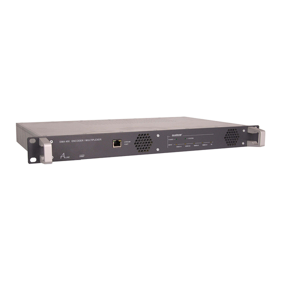
ENCODER/ MULTIPLEXER EMA x08/407 SDI/ A/V → ASI(TS) & IP(TS) Part N : 917x.xx LINE HDMI → ASI(TS) & IP(TS) 2. Explanation of the functional elements 2.1 Front view Fig. 1: Front view - in this case: EMA 408 POWER (green) LED on Device switched on System (green) LED on Internal system components are ready for operation. -
Page 7: Pole Allocation Of The Audio Sockets (Ema 308, 407, 408, 608)
HDMI → ASI(TS) & IP(TS) 2.2.2 Pole allocation of the audio sockets (EMA 308, 407, 408, 608) The audio input ports are symmetrical. If they are used asymmetrically, pin 1 and 3 must be allocated as signal lines and pin 4, 5 and 2 as return lines (shielding/ ground). -
Page 8: Operating Instructions
To change the configuration, the HTML user interface is provided via the Ethernet interface (see section 3.3). The adjustments of the installed encoder cards are set to the respective encoder mode automatically. The basic settings of the EMA devices are shown in the following table: EMA 308 EMA 407 EMA 408/ 508/ 608/ 708 IP address: 192.168.2.86... -
Page 9: Configurations Via The Ethernet Interface
ENCODER/ MULTIPLEXER EMA x08/407 SDI/ A/V → ASI(TS) & IP(TS) Part N : 917x.xx LINE HDMI → ASI(TS) & IP(TS) EMA 308 EMA 407 EMA 408/ 508/ 608/ 708 Channel Mux: Channel Mux: Channel Mux: ASI output mode: continous ASI output mode: continous ASI output mode:... -
Page 10: Configuration Menu (Html Page)
ENCODER/ MULTIPLEXER EMA x08/407 SDI/ A/V → ASI(TS) & IP(TS) Part N : 917x.xx LINE HDMI → ASI(TS) & IP(TS) 3.3.2 Configuration menu (HTML page) The configuration menu will appear on successful log-in. It is divided into the two following sections: 1. Status information and help functions Change Passwort, Help, Factory setting, Set Date & Time and Status xxx (if enabled) 2. -
Page 11: General Selection
Slot A..D (Encoder moduls):[OFF/ CVBS/ SDI, emb. Audio/ SDI, anal. Audio/ [ASI-TS]/ [CVBS-SPDIF]/ [SDI-SPDIF]/ Intern/ Transcoder / Decoder] The hardware configuration is automatically detected. The purpose of their possible modes are provided. “OFF“ Module deactiviated. “CVBS“ (available in EMA 308, 408, 608) The input signal is an analogue A/V signal (SD). -
Page 12: Asi Main Input
HDMI → ASI(TS) & IP(TS) “SDI embedded Audio“ The input signal is a serial digital video signal (MPEG-2 only SD-SDI) with integrated audio (AES-EBU, 48kHz), teletext (WST/ PAL) is possible. “SDI analog Audio“ (available in EMA 308, 407, 408, 608) Input signal SDI with possible teletext and analogue audio input. [ASI-TS], [CVBS-SPDIF], [SDI-SPDIF] (option with restrictions): (available in EMA 308, 408, 608) “CVBS-SPDIF“/ “SDI-SPDIF“... -
Page 13: Slot A (Input A) Parameters
LINE HDMI → ASI(TS) & IP(TS) 3.3.2.2.4 Slot A (Input-A) parameters All the following setting notes apply equally to encoders B ... D. Fig. 12: Setting of encoder parameters for the individual input channels Fig. 13: Setting of encoder parameters for the individual input channels (EMA 408, SDI input signal) (EMA 308, analogue input signal) Program Name: Assignment of a name for each imported or transformed program. The program name is displayed on the terminal equipment (TV). The program name must be unique and may appear only once in a cascade of encoders. The maximum length is 16 characters. Program Language: [deu, eng, ...] Identifies the language for the audio data stream and teletext. It should be designated as per ISO 639-2 [4]. -
Page 14: Additional Data → Mux
ENCODER/ MULTIPLEXER EMA x08/407 SDI/ A/V → ASI(TS) & IP(TS) Part N : 917x.xx LINE HDMI → ASI(TS) & IP(TS) Audio Input Level (analogue): Adaption of the audio level at the input. TTX Processing: [OFF, Video IN, Intern (ViTex)] “OFF“ Feature deactivated. -
Page 15: Channel Mux (Settings For The Transport Stream)
ENCODER/ MULTIPLEXER EMA x08/407 SDI/ A/V → ASI(TS) & IP(TS) Part N : 917x.xx LINE HDMI → ASI(TS) & IP(TS) 3.3.2.2.6 Channel MUX (settings for the transport stream) Fig. 13: Parameter settings for the transport stream configuration ASI Output Mode: [Continuous/ Burst] “Continuous Mode“ All the bytes in the output stream have a fixed temporal distance from each other. The maximum data rate in this mode is 98 Mbps. -
Page 16: System Parameters
ENCODER/ MULTIPLEXER EMA x08/407 SDI/ A/V → ASI(TS) & IP(TS) Part N : 917x.xx LINE HDMI → ASI(TS) & IP(TS) Device within Cascade: [1..8] Device number: to distinguish the installed devices within a cascade. It is used to generate unique program numbers (service ID) and PID‘s automatically. Table Extension: [OFF, ON] Extension of the device configuration via script programming (expert mode, for example to affect the automatic generated PID and SID). -
Page 17: Ip Streaming
ENCODER/ MULTIPLEXER EMA x08/407 SDI/ A/V → ASI(TS) & IP(TS) Part N : 917x.xx LINE HDMI → ASI(TS) & IP(TS) 3.3.2.2.8 IP streaming Depending on the selection under “General Selection“ (see also 3.3.2.2.2) different input masks are available: Selection: “Simple UDP (rear)“ - Streaming via control port Fig. 15: Parameter settings streaming via control port In this mode, all the services of ASI Out TS signal are outputed via the control port. The data rate of IP stream is thus determined directly from the TS-OUT bit rate of the system (settings see 3.3.2.2.6 Channel MUX) From the control port provided bandwidth is suffici- ent to output services with a total of 20 Mbps on the specified destination (IP address/ steaming port). -
Page 18: Transcoder Operating Modes
ENCODER/ MULTIPLEXER EMA x08/407 SDI/ A/V → ASI(TS) & IP(TS) Part N : 917x.xx LINE HDMI → ASI(TS) & IP(TS) Example1: - stream N - stream activated - sends to target address 192.168.10.78, port 6200 - with UDP protocol - FEC modes on UDP without functionality - “Present/ Following“... -
Page 19: Ema 408-Transcoder, Mpeg-2 To H.264/ Avc
ENCODER/ MULTIPLEXER EMA x08/407 SDI/ A/V → ASI(TS) & IP(TS) Part N : 917x.xx LINE HDMI → ASI(TS) & IP(TS) 3.3.3.1 EMA 408 transcoder, MPEG-2 to H.264/ AVC Example: A MPEG-2 service from the ASI input signal is transcoded to H.264/ AVC. ASI input is activated. Encoder in slot A is set to transcoder operation mode. -
Page 20: Ema 407-Transcoder, H.264/ Avc To Mpeg-2
ENCODER/ MULTIPLEXER EMA x08/407 SDI/ A/V → ASI(TS) & IP(TS) Part N : 917x.xx LINE HDMI → ASI(TS) & IP(TS) 3.3.3.2 EMA 407 Transcoder, H.264/ AVC to MPEG-2 Example: A H.264/ AVC service from the ASI input signal is transcoded to MPEG-2 SD. Maximum 2 per unit, services can be implemented in this mode. ASI input is activated. -
Page 21: Detailed Configuration (For Single And Multiple Device Systems)
ENCODER/ MULTIPLEXER EMA x08/407 SDI/ A/V → ASI(TS) & IP(TS) Part N : 917x.xx LINE HDMI → ASI(TS) & IP(TS) 3.3.4 Detailed configuration (for single and multiple device systems) Depending on the task and the desired number of channels per DVB transport stream, the devices can be operated individually or in groups (cascades) of up to 8 devices. - Page 22 ENCODER/ MULTIPLEXER EMA x08/407 SDI/ A/V → ASI(TS) & IP(TS) Part N : 917x.xx LINE HDMI → ASI(TS) & IP(TS) • Network ID: This identifies the distribution network (the head end); all transport streams generated or processed in a head end are given the same network ID. The following settings must be unique to the relevant device or will be taken account of by only one device in the cascade: • IP address: The IP address of each device must be unique within the IP network.
-
Page 23: Transport Stream Bit Rate (Ts Out Bitrate), System Bit Rate
ENCODER/ MULTIPLEXER EMA x08/407 SDI/ A/V → ASI(TS) & IP(TS) Part N : 917x.xx LINE HDMI → ASI(TS) & IP(TS) Note: The SID/ PID for the slots configured (the programs and channels) is automatically allocated according to a fixed pattern. Inserting de- tails of the device in the cascade and the number of the cascade ensures that the values will not overlap. -
Page 24: Special Configuration Via Table Script
ENCODER/ MULTIPLEXER EMA x08/407 SDI/ A/V → ASI(TS) & IP(TS) Part N : 917x.xx LINE HDMI → ASI(TS) & IP(TS) The following settings and functions are possible: Switches State Function TTX processing No teletext or VPS and WSS data adopted. TTX processing Video-IN Teletext data from lines 7 to 15, 19 to 22, 320 to 328 and 332 to 335, will digitalised and transmitted in the DVB transport stream. -
Page 25: Options
C. Factory setting with the aid of the maintenance software (via RS 232): The maintenance software is a Windows PC program module obtainable from BLANKOM Antennentechnik GmbH which will create the factory settings. Firstly, the maintenance software has to be installed on the control PC and a cable connection must be established bet- ween this and the EMA device. -
Page 26: Integration Into The Head End Management System For B-Line Or C-Line
ENCODER/ MULTIPLEXER EMA x08/407 SDI/ A/V → ASI(TS) & IP(TS) Part N : 917x.xx LINE HDMI → ASI(TS) & IP(TS) 3.4.6 Integration into the head end management system for B-LINE or C-LINE If a EMA device is being used in association with B- or C-LINE head end components, the possibility exists (using HCB x00 “BLUE“, from 9650.03 upwards) of integrating the encoder into the overview of the head end and calling it up from this screen. -
Page 27: Appendix
SDI/ A/V → ASI(TS) & IP(TS) Part N : 917x.xx LINE HDMI → ASI(TS) & IP(TS) 4. Appendix 4.1 Technical data EMA 308 EMA 407 EMA 408 EMA 508 EMA 608 EMA 708 Casing/ dimensions for installation 19“ rack, 1 RU (steel sheet) HxWxD = 44 x 444 √... -
Page 28: Accessories
ENCODER/ MULTIPLEXER EMA x08/407 SDI/ A/V → ASI(TS) & IP(TS) Part N : 917x.xx LINE HDMI → ASI(TS) & IP(TS) EMA 308 EMA 407 EMA 408 EMA 508 EMA 608 EMA 708 Transport stream (DVB-ASI) with MPEG-2 HD/SD √ √... -
Page 29: Optional Accessories
(for cable diameter 6 mm) DIN plug, 8 poles SV 081 0141 ... length as specified by customer Further accessories are to be found in the BLANKOM Antennentechnik main catalogue. 4.3 Glossary and abbreviations Term Meaning Notes Asynchron Serial Interface... - Page 30 ENCODER/ MULTIPLEXER EMA x08/407 SDI/ A/V → ASI(TS) & IP(TS) Part N : 917x.xx LINE HDMI → ASI(TS) & IP(TS) Term Meaning Notes Kbps Bit rate Kilo Bit per second (where Kilo=1024) Load Reads out the parameter settings of the EMA de- The parameters can be viewed and altered.
-
Page 31: Bibliography
Häußer 1.01 20.05.2011 revision accessories Häußer 1.02 25.08.2011 additions chapter 4.1 Häußer 1.03 28.10.2011 correction SPDIF Häußer 1.04 19.06.2012 insert the EMA 508...708 devices Häußer 1.05 24.07.2013 revision, especially EMA 508, 708 Häußer Options available upon request. Subjects to changes due to technical progress. BLANKOM Antennentechnik GmbH Hermann-Petersilge-Straße 1 • 07422 Bad Blankenburg • Germany • Phone +49 (0) 3 67 41 / 60-0 • Fax +49 (0) 3 67 41 / 60-100... -
Page 32: Declaration Of Conformity
07422 Bad Blankenburg Germany Product Name: Encoder/ Multiplexer Type Name: EMA 308, EMA 407, EMA 408, EMA 508, EMA 608, EMA 708 Type N 9173.81, 9173.82, 9174.71, 9174.72, 9174.81, 9174.82, 9175.81, 9175.82, 9176.81, 9176.82, 9177.81, 9177.82 BLANKOM Antennentechnik GmbH confirms that the mentioned products meet the guideline(s) of the Council for the approximation of legislation of the member states.
Need help?
Do you have a question about the EMA 308 and is the answer not in the manual?
Questions and answers