YASKAWA SOLECTRIA XGI 1500 Installation And Operation Manual
Commercial 1500vdc string inverter
Hide thumbs
Also See for SOLECTRIA XGI 1500:
- Installation and operation manual (77 pages) ,
- Manual (30 pages)

Related Manuals for YASKAWA SOLECTRIA XGI 1500


Summary of Contents for YASKAWA SOLECTRIA XGI 1500
- Page 1 Commercial 1500VDC String Inverter SOLECTRIA XGI™ 1500 Installation and Operation Guide Models: XGI 1500-125/125-UL XGI 1500-125/150-UL XGI 1500-150/166-UL XGI 1500-166/166-UL XGI 1500-125/125-3S XGI 1500-166/166-3S...
-
Page 2: Table Of Contents
Installation and Operation Guide SOLECTRIA XGI 1500 (Rev E, 5 Mar. 2021) Table of Contents IMPORTANT SAFETY INSTRUCTIONS ....................4 Hazard Symbols ..........................4 Symbols on Labels ..........................4 General Safety Messages ........................5 Status Panel ............................6 Overview ..............................7 Inverter Overview .......................... - Page 3 Installation and Operation Guide SOLECTRIA XGI 1500 (Rev E, 5 Mar. 2021) Networking with Other Devices ......................36 Monitoring Compatibility ........................37 Third-Party Data Acquisition System (DAS) Connection ..............37 Static IP Configuration, Gateway Inverter ..................38 Port Forwarding ..........................38 Static Routing ............................
-
Page 4: Important Safety Instructions
Installation and Operation Guide SOLECTRIA XGI 1500 (Rev E, 5 Mar. 2021) IMPORTANT SAFETY INSTRUCTIONS Hazard Symbols Table 1-1 Hazard Symbols DANGER indicates a hazardous situation, which, if not avoided, will result in serious injury or death. WARNING indicates a hazardous situation, which, if not avoided, could result in serious injury or death. -
Page 5: General Safety Messages
Installation and Operation Guide SOLECTRIA XGI 1500 (Rev E, 5 Mar. 2021) General Safety Messages Electric Shock Hazard Components with hazardous voltage and energy will electrocute operator. Operator shall avoid touching live components with hazardous voltage and energy. Unqualified Operator Hazard Operator may cause a hazardous situation by making incorrect installation or wiring connections. -
Page 6: Status Panel
Installation and Operation Guide SOLECTRIA XGI 1500 (Rev E, 5 Mar. 2021) Status Panel The status panel consists of five LEDs that provide useful information to the user regarding the function of the inverter. LEDs are shown in Figure 1-1 and defined in Table 1-3. -
Page 7: Overview
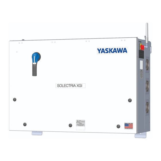
A solar inverter converts DC power from solar modules to AC power, and exports it to the electrical grid as shown in Figure 2-1. The SOLECTRIA XGI 1500 is a state-of-the-art inverter designed and made in the USA using global components and is compliant with the Buy American Act. - Page 8 2.1.3 Communication Overview Users can communicate with the SOLECTRIA XGI 1500 using a Wi-Fi-enabled smart device, such as a laptop, tablet, or smartphone. The SOLECTRIA XGI 1500 monitors internal variables which are sent via a modem or gateway to the Internet cloud. In the cloud, these data are stored on the SRV server where they can be accessed by the end user (additional fee applies).
- Page 9 Installation and Operation Guide SOLECTRIA XGI 1500 (Rev E, 5 Mar. 2021) 2.1.4 Inverter Features Figure 2-3 SOLECTRIA XGI 1500 Inverter Features: Front (Left), Right Side (Right), and Bottom (Bottom) 9 of 70...
-
Page 10: Inverter Placement
Inverter Placement The SOLECTRIA XGI 1500 inverter is rated for outdoor use and will operate when exposed to direct sunlight or rain. To obtain the best performance and insure longevity of the inverter, it is recommended to mount the inverter out of the direct sunlight. -
Page 11: Unpacking
Installation and Operation Guide SOLECTRIA XGI 1500 (Rev E, 5 Mar. 2021) Unpacking When storing the packaged inverters, keep them in an area where they will not get damaged or flooded. Storage temperatures should be maintained in the range -40°F to +167°F (-40°C to +75°C). Open the box carefully to avoid damaging the contents. -
Page 12: Inverter Size, Spacing And Mounting
Installation and Operation Guide SOLECTRIA XGI 1500 (Rev E, 5 Mar. 2021) Inverter Size, Spacing and Mounting The dimensions of the XGI 1500 inverter are shown in Figure 3-1. 41.3 in 1048 mm 34.9 in 34.9 in 886 mm 886 mm... - Page 13 Installation and Operation Guide SOLECTRIA XGI 1500 (Rev E, 5 Mar. 2021) Use Figure 3-3 to space strut channels for mounting. The holes on the bottom use the center as the reference point and the hook at the top uses the top of the upper strut channel as its reference point. Use two 8 mm ( in) bolts (not provided) to connect the bottom brackets to the strut channel.
- Page 14 Installation and Operation Guide SOLECTRIA XGI 1500 (Rev E, 5 Mar. 2021) When positioned on the strut, the inverter and strut channels should appear as in Figure 3-5. To secure the inverter in place, use two 8mm ( in) bolts (not provided) through the holes provided in the top face of the upper brackets, and two more through the front face of the lower bracket.
-
Page 15: Wiring
Installation and Operation Guide SOLECTRIA XGI 1500 (Rev E, 5 Mar. 2021) Wiring Turn the AC Switch to OFF before wiring. The AC switch is located on the right side of the inverter (Figure 2-3.) Turn AC Switch to OFF Verify the absence of AC voltage. - Page 16 Installation and Operation Guide SOLECTRIA XGI 1500 (Rev E, 5 Mar. 2021) With the cover removed, the inverter is ready for wiring, as shown in Figure 3-7. Figure 3-7 Wiring Box Connections 3.3.2 Removable Conduit Panel All conduit entries must pass through the removable conduit panel. All modifications to the removable panel must occur when the panel is detached from the inverter.
- Page 17 Installation and Operation Guide SOLECTRIA XGI 1500 (Rev E, 5 Mar. 2021) Figure 3-8 Removable Conduit Panel – Entry Locations 17 of 70...
- Page 18 Installation and Operation Guide SOLECTRIA XGI 1500 (Rev E, 5 Mar. 2021) Figure 3-9 DC Conduit Hole Location for Inverters Paired with Attachable Combiners Figure 3-10 Conduit Hole Location for Attachable Combiners 18 of 70...
-
Page 19: Transformer Configuration
Installation and Operation Guide SOLECTRIA XGI 1500 (Rev E, 5 Mar. 2021) Transformer Configuration Grid Mismatch If the grid does not match the requirements, the inverter will not start and damage may occur. Check with your local electric utility before selecting a grid standard. -
Page 20: Equipment Grounding
Installation and Operation Guide SOLECTRIA XGI 1500 (Rev E, 5 Mar. 2021) Figure 3-12 Prohibited Transformer Configurations Equipment Grounding Improper Transformer Configuration Inverter will not run and may have hazardous current. Connect transformer in specified configurations only. Incorrect transformer configuration may cause damage to the inverter. - Page 21 Installation and Operation Guide SOLECTRIA XGI 1500 (Rev E, 5 Mar. 2021) 2 to 1/0 AWG 2 to 1/0 AWG 2 to 1/0 AWG 2 to 1/0 AWG (33.6 to 53.5 mm (33.6 to 53.5 mm (33.6 to 53.5 mm (33.6 to 53.5 mm...
-
Page 22: Ac Connections
Installation and Operation Guide SOLECTRIA XGI 1500 (Rev E, 5 Mar. 2021) AC Connections The AC connections consist of the 3 AC Phases (L1, L2, and L3), Neutral and Ground. AC wires must be rated for at least 600 VAC. Use wires within the ranges shown in Table 3-2, and sized as required to comply with local and National electrical codes. -
Page 23: Ac Breaker Specifications
AC conductors will reverse the phase rotation. AC Breaker Specifications The AC output of the Solectria XGI 1500 series inverters requires connection to a 3-pole AC breaker with ratings as specified in Table 3-3. Table 3-4 AC Breaker Specifications... -
Page 24: Dc Connections
3.8.1 General DC Connection Information The SOLECTRIA XGI 1500 is a single DC input into one MPPT zone. Perform the calculations based on the total inverter nameplate AC power rating. With the maximum DC/AC ratios shown in Table 3-5, at STC conditions (Equation 3.1), a user can connect up to 332 kWp for all XGI 1500 models. -
Page 25: Dc Connection Using The Xgi Remote Or Attachable Combiner
Installation and Operation Guide SOLECTRIA XGI 1500 (Rev E, 5 Mar. 2021) 3.8.3 Fuses Configuration and Sizes Refer to Table 3-6 for information regarding fuse sizes and configuration. Table 3-6 Attachable Combiner Box Number of DC Inputs 16, 20, 24, 26, 28... - Page 26 Installation and Operation Guide SOLECTRIA XGI 1500 (Rev E, 5 Mar. 2021) Table 3-7 DC Input Wire Size XGI 1500-125/125 XGI 1500-125/150 XGI 1500-150/166 XGI 1500-166/166 Minimum Wire Size 2/0 AWG 2/0 AWG 3/0 AWG 4/0 AWG (Copper) (67.4 mm (67.4 mm...
-
Page 27: Dc Connection Using The Xgi Attachable Combiner Box
Installation and Operation Guide SOLECTRIA XGI 1500 (Rev E, 5 Mar. 2021) DC Connection Using the XGI Attachable Combiner Box Figure 3-17 XGI 1500V with Attachable Combiner Box Option Electric Shock Hazard Components with hazardous voltage and energy pose the risk of electrocuting operators. - Page 28 Installation and Operation Guide SOLECTRIA XGI 1500 (Rev E, 5 Mar. 2021) Crimp lugs for terminations on posts in Combiner and XGI wiring compartment. (2) 4/0 AWG, RHW-2 2000V 90°C Cu GND #4 AWG, RHW-2 2000V 90°C Cu Red = positive, black = negative...
-
Page 29: Conduit Sealing
Installation and Operation Guide SOLECTRIA XGI 1500 (Rev E, 5 Mar. 2021) Conduit Sealing All conduit entrances must be sealed conduit foam. Ensure to use a product that is listed for use in electrical applications. Polywater ® ATF Spray Foam Sealant is an excellent option. Follow the manufactures recommendations when sealing conduit entrances. -
Page 30: Antenna Mounting
Installation and Operation Guide SOLECTRIA XGI 1500 (Rev E, 5 Mar. 2021) Antenna Mounting Mount the antenna as shown in Figure 3-19. The antenna works best when oriented vertically. Figure 3-19 Mounting the Antenna Replace Wiring Box Cover Put the cover back on the inverter. Use a #3 Phillips head torque driver to tighten the cover screws to 40 in-lbs (4.5 N-m). -
Page 31: Startup And Verification Test
Installation and Operation Guide SOLECTRIA XGI 1500 (Rev E, 5 Mar. 2021) Startup and Verification Test Electrical Shock Hazard Installer may come into contact with components that have hazardous voltage and energy. Use proper safety equipment when energizing the inverter. -
Page 32: Commissioning Test
Installation and Operation Guide SOLECTRIA XGI 1500 (Rev E, 5 Mar. 2021) Verify that the Status Panel illuminates READY and that neither MAINTENANCE nor POWER FAULT LED is illuminated. If the LEDs are not in this state, see Section 9 Maintenance and Troubleshooting. -
Page 33: Communication Installation And User Interface
Installation and Operation Guide SOLECTRIA XGI 1500 (Rev E, 5 Mar. 2021) Communication Installation and User Interface The SOLECTRIA XGI inverters utilize an advanced communication platform that can be accessed over WiFi using a smart device, or over Ethernet using a PC. - Page 34 Installation and Operation Guide SOLECTRIA XGI 1500 (Rev E, 5 Mar. 2021) XGI Inverters can be clustered using Ethernet daisy chains (Figure 5-1Error! Reference source not found.), mixed networks using Ethernet switches (Figure 5-2), or any combination to form a multi-cluster configuration (Figure 5-3).
- Page 35 Installation and Operation Guide SOLECTRIA XGI 1500 (Rev E, 5 Mar. 2021) Figure 5-2 Mixed network 35 of 70...
-
Page 36: Xgi Gateway Inverters Firewall
Installation and Operation Guide SOLECTRIA XGI 1500 (Rev E, 5 Mar. 2021) Cluster A INV A1, Gateway INV An Inverter Firewall Switch Optional, Long Haul Fiber Modem or Cluster B Internet Gateway Switch or Internet INV B1, Gateway INV Bn... -
Page 37: Monitoring Compatibility
Installation and Operation Guide SOLECTRIA XGI 1500 (Rev E, 5 Mar. 2021) Cluster LAN - All other Ethernet devices - - XGI Inverters Only - Modem or INV 1, Gateway INV 50 INV 49 INV 2 Internet Inverter Gateway Internet... -
Page 38: Static Ip Configuration, Gateway Inverter
Installation and Operation Guide SOLECTRIA XGI 1500 (Rev E, 5 Mar. 2021) Static IP Configuration, Gateway Inverter Gateway inverters can be manually configured using a static IP. It is important to identify which Ethernet Port is configured with the static IP and ensure this is connected to the LAN. Once a static IP is configured the port will no longer function as a Cluster connection. - Page 39 Installation and Operation Guide SOLECTRIA XGI 1500 (Rev E, 5 Mar. 2021) By default the Gateway Inverter will detect and recommend an IP/Subnet from which external devices are allowed through the Inverter Gateway Firewall. For security purposes the user is encouraged to enter the most restrictive value, with preference given to the specific IP address of the external device (DAS).
-
Page 40: Static Routing
Installation and Operation Guide SOLECTRIA XGI 1500 (Rev E, 5 Mar. 2021) Figure 5-7 Port Forwarding 5.9.3 Port Forwarding, DAS Configuration The External Access IP and respective Port settings must be configured on the third-party monitoring platform or DAS. This will allow the DAS to query the desired inverter properly. -
Page 41: Manage Cluster Ip Address
Installation and Operation Guide SOLECTRIA XGI 1500 (Rev E, 5 Mar. 2021) Figure 5-8 Enabling external Modbus access, static routing 5.10.2 Static Routing, Entering Static Routing Rule on LAN A static routing rule can be implemented on any permanently installed device on the LAN. Most commonly this is configured on the Internet Gateway Modem/Router or the third-party DAS (if feature is provided). -
Page 42: Communication And I/O Ports
Installation and Operation Guide SOLECTRIA XGI 1500 (Rev E, 5 Mar. 2021) Figure 5-9 Manage IP Configuration Communication and I/O Ports The SOLECTRIA XGI has two interchangeable Ethernet Ports. These connections are located in the right hand compartment within the Wire Box. -
Page 43: Graphical User Interface
Installation and Operation Guide SOLECTRIA XGI 1500 (Rev E, 5 Mar. 2021) Graphical User Interface The XGI series of inverters operate on an advanced communication platform that provides the operator with an unparalleled level of access and control. The user interface is designed to be intuitive and easy to use, however, it is important to understand the supported network topologies and some XGI specific terminology that is used within this document. - Page 44 Installation and Operation Guide SOLECTRIA XGI 1500 (Rev E, 5 Mar. 2021) INFO ✔ ✔ ✔ ✔ No Built in Keypad: To provide a more robust GUI and remove a common failure point, the XGI does not contain a built in keypad. The XGI has an LED Status Panel that provides a visual indication of the inverter status but does not allow the user to control the inverter.
- Page 45 Installation and Operation Guide SOLECTRIA XGI 1500 (Rev E, 5 Mar. 2021) 6.2.2 Connecting to the Inverter, WiFi To access the inverter using WiFi, connect the smart device or laptop to the WiFi network (see for default SSID). Wait 15 seconds for the laptop to obtain an IP address from the XGI Inverter. Open your preferred web browser (example Firefox or Chrome) and type xgi.solar in the address bar, then click Enter to navigate to the website.
- Page 46 Installation and Operation Guide SOLECTRIA XGI 1500 (Rev E, 5 Mar. 2021) Figure 6-1 Inverter List Example Table 6-3 Explanation of Symbols in User Interface Symbol Explanation Inverter OK: This indicates that the inverter is on the Reference List and functioning normally.
- Page 47 Installation and Operation Guide SOLECTRIA XGI 1500 (Rev E, 5 Mar. 2021) Figure 6-2 Inverter Home Page (Observer Mode) Selecting the inverter status icons will give their current state, as shown in . Figure 6-3 Current Status with Network and Communication Working and Maintenance with an Event The menu button is located in the upper left corner, represented by three horizontal lines (≡).
- Page 48 Installation and Operation Guide SOLECTRIA XGI 1500 (Rev E, 5 Mar. 2021) 6.2.5 Logging In Before logging in, the user interface is in observer mode. Logging in is necessary to view and access the Inverter Configurations options in the menu in administrator mode. Everything that is accessible in observer mode is also accessible in administrator mode.
-
Page 49: Menu Structure
Installation and Operation Guide SOLECTRIA XGI 1500 (Rev E, 5 Mar. 2021) Menu Structure This menu structure is subject to change as firmware updates are released. Inverter List Jump to Other Select Inverter Inverters in to View Cluster Home Live... -
Page 50: Firmware Updates
Firmware Updates SOLECTRIA XGI inverters support local and remote firmware updates. Remote updates are performed automatically from the Yaskawa Solectria Solar server or manually via the Remote Access Portal (with subscription). Local firmware updates can be performed with a laptop and an Ethernet cable. - Page 51 Installation and Operation Guide SOLECTRIA XGI 1500 (Rev E, 5 Mar. 2021) Figure 7-1 Firmware Update 51 of 70...
-
Page 52: Communication Commissioning
Installation and Operation Guide SOLECTRIA XGI 1500 (Rev E, 5 Mar. 2021) Communication Commissioning Once all inverters are installed and energized, the XGI communications can be commissioned. Before proceeding ensure that the following conditions are met: All inverters energized, (DC voltage) ... -
Page 53: Maintenance And Troubleshooting
Installation and Operation Guide SOLECTRIA XGI 1500 (Rev E, 5 Mar. 2021) Maintenance and Troubleshooting If an inverter is not running correctly, the Status Panel will show that there is an issue. When the inverter is working normally, the three leftmost LEDs are lit (Ready, Network and Communications, and Power) and the two on the right will be off (Maintenance and Power Fault). - Page 54 Installation and Operation Guide SOLECTRIA XGI 1500 (Rev E, 5 Mar. 2021) One or both of the AC grid Power cycle the inverter. If the AC Contactor contactors has failed. Contactors inverter doesn’t clear the error, Failure may fail open or closed.
- Page 55 Installation and Operation Guide SOLECTRIA XGI 1500 (Rev E, 5 Mar. 2021) 9.1.2 Warning Events Warning events will always result in the inverter ceasing AC power production, but the inverter can self-recover if conditions causing the event cease. A warning event is indicated by the inverter illuminating the Maintenance LED (wrench).
- Page 56 Installation and Operation Guide SOLECTRIA XGI 1500 (Rev E, 5 Mar. 2021) Using a CAT III multi-meter verify the AC frequency. If there is a discrepancy AC Very High of greater than 2% between the AC high frequency region 2...
- Page 57 Installation and Operation Guide SOLECTRIA XGI 1500 (Rev E, 5 Mar. 2021) Power cycle the inverter. If the inverter Communication Communication processor doesn’t clear the error, contact 3 Fault hardware fault. Technical Support. Check to make sure the Ethernet connections are firmly seated. Check Network Fault A network connection has failed.
-
Page 58: Regular Preventative Maintenance
Installation and Operation Guide SOLECTRIA XGI 1500 (Rev E, 5 Mar. 2021) Regular Preventative Maintenance Solectria’s warranty terms require regular preventative maintenance. It is recommended to perform this service annually, adjusting the service interval as needed depending on site conditions. It may be necessary to perform the preventative maintenance more frequently during the first year to determine the appropriate service interval. - Page 59 Installation and Operation Guide SOLECTRIA XGI 1500 (Rev E, 5 Mar. 2021) Figure 9-1 Inverter Wiring Box 5. While the cover is off, perform a visual inspection of the wiring box compartment, looking for water, excessive debris, discoloration of components, quality of workmanship, pests, or anything else that may interfere with proper inverter operation.
- Page 60 Installation and Operation Guide SOLECTRIA XGI 1500 (Rev E, 5 Mar. 2021) Figure 9-2 Inverter Fan Gaurds Debris may also collect in the cooling plenum, on the heatsinks, and inductors located in this section of the inverter. A removable panel located at the rear of the inverter provides access for cleaning.
- Page 61 Installation and Operation Guide SOLECTRIA XGI 1500 (Rev E, 5 Mar. 2021) To clean the cooling plenum: 1. Turn off the inverter, first by moving the DC Switch on the inverter to the “OFF” position, then by turning the AC Switch on the inverter to the “OFF” position.
-
Page 62: Specifications
Installation and Operation Guide SOLECTRIA XGI 1500 (Rev E, 5 Mar. 2021) Specifications General Specifications Table 10-1 General Specifications XGI 1500-125/125 XGI 1500-125/150 XGI 1500-150/166 XGI 1500-166/166 Max Input Voltage 1500 VDC Full Power Input 860 to 1250 VDC 860 to 1250 VDC... -
Page 63: Voltage And Frequency Limits And Trip Times
Installation and Operation Guide SOLECTRIA XGI 1500 (Rev E, 5 Mar. 2021) Voltage and Frequency Limits and Trip Times All models of the SOLECTRIA XGI 1500 comply with IEEE1547-2003 requirements. The tables below show its standard settings. Table 10-3 Default Voltage Limits and Trip Times Clearing Time Adjustable Up to Voltage Range (±... -
Page 64: Temperature And Altitude
Installation and Operation Guide SOLECTRIA XGI 1500 (Rev E, 5 Mar. 2021) Figure 10-2 Derating with DC Voltage Temperature and Altitude Table 10-5 Normal Temperature Ranges Ambient Temperature Range -40°F to +140°F (-40°C to +60°C) Derating Temperature 113°F (45°C) Storage Temperature Range -40°F to +167°F (-40°C to +75°C) - Page 65 Installation and Operation Guide SOLECTRIA XGI 1500 (Rev E, 5 Mar. 2021) % of Rated Full Power vs Altitude Altitude (km) Figure 10-4 Derating with Altitude 65 of 70...
-
Page 66: Options
Figure 11-1 Illustration of XGI 1500 Combiner Usage Attachable Combiner Box (Optional) The SOLECTRIA XGI 1500 can be ordered with an optional Attachable Combiner (CA-XGI1500 series). The Attachable Combiner is intended to be installed immediately adjacent to the XGI 1500 inverter. This combination is typically used in distributed PV system architecture. - Page 67 Installation and Operation Guide SOLECTRIA XGI 1500 (Rev E, 5 Mar. 2021) Figure 11-2 SOLECTRIA XGI 1500 with the Attachable Combiner Box UPPER MOUNTING BRACKET FUSE HOLDERS 29.5 in. BUSBARS, + AND - (750mm) GROUND TERMINAL LOWER MOUNTING BRACKET 10.6 in.
-
Page 68: Remote Combiner (Optional)
Installation and Operation Guide SOLECTRIA XGI 1500 (Rev E, 5 Mar. 2021) Remote Combiner (Optional) Yaskawa Solectria Solar also offers a Remote Combiner (CR-XGI1500 series) that is exclusively compatible with the XGI 1500. The Remote Combiner is intended to be installed in the vicinity of the PV array and is typically used when the inverters are clustered in a “virtual central”... -
Page 69: Appendix
Installation and Operation Guide SOLECTRIA XGI 1500 (Rev E, 5 Mar. 2021) Appendix Warranty and RMA Instructions For all warranty information, please visit: http://solectria.com/support/documentation/warranty-information/grid-tied-inverter-warranty-letter/ Yaskawa Solectria Solar Contact Information Table 12-1 Yaskawa Solectria Solar Contact Information Telephone 978.683.9700 978.683.9702 Sales Support inverters@solectria.com... -
Page 70: Authorization To Mark
Installation and Operation Guide SOLECTRIA XGI 1500 (Rev E, 5 Mar. 2021) Authorization to Mark 70 of 70...
Need help?
Do you have a question about the SOLECTRIA XGI 1500 and is the answer not in the manual?
Questions and answers