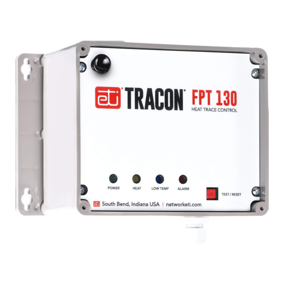
ETI Tracon FPT 130 Manual
Single–point freeze protection heat–trace control
Hide thumbs
Also See for Tracon FPT 130:
- Quick reference installation manual (5 pages) ,
- Manual (9 pages) ,
- Quick start manual (11 pages)
Table of Contents
Advertisement
TRACON
®
MODEL FPT-130
SINGLE-POINT FREEZE PROTECTION HEAT-TRACE CONTROL
TABLE OF CONTENTS
FPT 130 Overview.................................................................................... 2
Installation ................................................................................................ 3
Power Source and Load Connections................................................... 4
Temperature Sensor ................................................................................ 5
External Alarm .......................................................................................... 5
Dip Switches ............................................................................................. 6
Operation ................................................................................................. 7
Specifications ........................................................................................... 9
Pilot Duty
The FPT 130 General Purpose Thermostat with GFEP cannot be used
for Pilot Duty applications.
Resistive Load Usage Only
This product is not for use with Inductive loads. Inductive loads
may create nuisance tripping of the Ground-Fault Equipment
Protection circuit.
Abnormal Odor or Smoke
In the event of smoke or a burning or abnormal odor, immediately
interrupt power to the unit by turning off the circuit breaker protecting
the unit.
Electrical Shock / Fire Hazard
Any installation involving electric heater wiring must be grounded
to earth to protect against shock and fire hazard. Suitable ground
fault detection and interrupting systems must be in use at all times to
reduce shock and fire hazard and to protect equipment.
Electric wiring to heating elements must be installed in accordance
with National Electrical Code (NEC)/Canadian Electrical Code
requirements, as well as all other local and applicable electrical
codes and any thirdparty standards. This product is intended for
commercial and industrial applications. Follow the installation
South Bend, Indiana USA
|
networketi.com
FPT-130 INSTALLATION MANUAL | PART NO.
25165
REV
E
Advertisement
Table of Contents

Summary of Contents for ETI Tracon FPT 130
-
Page 1: Table Of Contents
TRACON ® MODEL FPT-130 SINGLE–POINT FREEZE PROTECTION HEAT–TRACE CONTROL TABLE OF CONTENTS FPT 130 Overview..................2 Installation ....................3 Power Source and Load Connections........... 4 Temperature Sensor ................5 External Alarm ..................5 Dip Switches ..................... 6 Operation ....................7 Specifications ................... -
Page 2: Fpt 130 Overview
instructions contained in this manual and those provided powered with an available line voltage source of 100 – 277 by the heater manufacturer. V ac. The controller and heater load are powered from the same supply connection. The internal load contactor are Size the circuit breaker appropriately for the expected rated to switch up to 30 A resistive. -
Page 3: Installation
INSTALLATION Use only Listed Type 4X IP66 liquid–tight conduit hubs The FPT 130 Automatic Heat–Trace Control should be installed by a qualified, licensed electrician. Installation or cable glands. Connect the hub to the conduit system must conform to all applicable local and national electrical before connecting the hub to the enclosure. -
Page 4: Power Source And Load Connections
FIGURE 2. Mounting dimensions COVER SCREWS Max Torque = 4 In-Lbs POWER SOURCE AND CONTACTOR CONNECTIONS Supply Voltage The FPT 130 operates from 100 – 277 V ac at 50/60 Hz. This control and its heater load should not share a circuit branch and circuit breaker with other types of equipment. -
Page 5: Temperature Sensor
FIGURE 4. Connection Schematic FIGURE 5. Thermistor sensor connection TEMPERATURE SENSOR Thermistor (25076) The FPT 130 comes with a thermistor temperature sensor with a 20 ft. jacketed cable that has an operating range of −40 °F to 230 °F (−40 ˚C to 110 ˚C). See Figure 5 for proper wiring for the thermistor sensor. -
Page 6: Dip Switches
DIP SWITCH SETTINGS FIGURE 7. FPT 130 DIP switch identification Note: The DIP switches are read at power-up. If any DIP switch is changed while the unit is on, then the power needs to be turned off and on again for the new setting to take effect. -
Page 7: Operation
Pushbuttons • TEST/RESET pushbutton – This red pushbutton has the The FPT 130 features ETI’s patented self–testing GFEP, following functions: which switches the system off when it detects excessive – To test the ground fault detector circuit itself AND... - Page 8 DISABLING THE LOW TEMP ALARM LED The blue LOW TEMP alarm LED indicates the presence of • The blue LED will indicate whether the LOW TEMP Low Temperature, High Temperature, or a bad thermistor. Alarm is currently disabled or not. When disabled this blue LED will only indicate for the –...
-
Page 9: Specifications
SPECIFICATIONS General User Interfaces Certifications UL 60730–1, UL 1053, Pushbuttons Test/Reset CSA E60730–1:13 DIP switches Temperature setpoint Environmental Thermistor fault mode Fire protection mode Area of use Nonhazardous locations Remote Interface Operating temperature range −40 °F to 122 °F (−40 °C to 50 °C) Alarm relay Isolated SPDT 1 AMP Class 2 Enclosure... - Page 10 For assistance, contact Customer Service. Office hours are changes and improvements to the products described from 8:00 AM until 5:00 PM ET. in this publication, without the obligation of ETI to notify Email: info@networketi.com any person or organization of such revisions, changes or improvements.


Need help?
Do you have a question about the Tracon FPT 130 and is the answer not in the manual?
Questions and answers
Will controller FPT **** work with 277v, self- regulating Thermon heat trace.
Yes, the ETI Tracon FPT 130 controller can work with a 277V self-regulating Thermon heat trace. The specifications indicate that the controller supports a load rating of 30A at 100–277V AC resistive, which aligns with the voltage requirements of a 277V heat trace system.
This answer is automatically generated