
Related Manuals for ETI PFC 6 RS


Summary of Contents for ETI PFC 6 RS
- Page 1 PFC 6 RS, PFC 8 RS Power factor correction controller User and service manual version 3.5 ETI d.d., Obrezija 5, SI-1411 Izlake www.etigroup.eu/support...
-
Page 2: Table Of Contents
Control and signal elements Device description Instruction manual for connection and operation Description of the function Installation of the device Controller parameter setting Target cosφ setting (CoS) 6.1. 6.2. Current transformer ratio setting (Itr) 6.3. Automatic detection of compensation stages (Aut) 6.4. -
Page 3: Control And Signal Elements
5. LED alarm – it is ON when alarm is present 6. LED STAGES – those LEDs indicate status of each stage individually 7. Buttons for regulator control Picture 2. Device terminal connection PFC 6 RS and PFC 8 RS... -
Page 4: Device Description
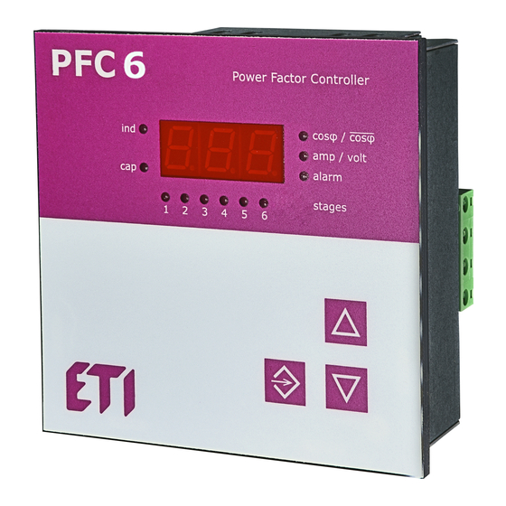
Device description Power factor correction regulator PFC 6 and PFC 8 are designed for reactive power control in low and medium voltage girds 50/60 Hz. PFC 6 and PFC 8 allows to control compensation cabinets with 6 (PFC 6) respective 8 (PFC 8) contactor steps. -
Page 5: Description Of The Function
will turn On. Another pressing the button SET will make the value of the power of the first stage be shown on the display. If the value is not correct, it should be changed by pressing buttons ▲, ▼ until the correct value. In the case of capacitor stage, LED cap, placed at the left side of display, has to light. -
Page 6: Controller Parameter Setting
Picture 5. Connection of PFC 8 controller for standard supply voltage 400 VAC Controller parameter setting Considering various usage of controllers PFC 6 and PFC 8, there is a number of programmable parameters. For easy start, regulator is set to default parameters, made by manufacturer. Set parameters are stated in the following table. - Page 7 manual setting of compensation stages 999 kVAr C ... 999 kVAr L in step of 0,1kvar discharging time for contactor stage, read chapter 6.6 ! 5 ... 900 s in step of 5 s or overdrive of 50 s delay for disconnection of contactor stage 5 ...
-
Page 8: Target Cosφ Setting (Cos)
10 ... 80°C temperature level for ventilator start device ID number in RS485 network 0 ... 255 communication speed for data transmission 0 ... 38,4 kBd communication control by parity checking oFF / on / on_o manual mode activation password for access to SET mode any three digits number 001 ... -
Page 9: Discharging Time (Dit)
Discharging time can be set from 5 to 900 seconds. Default factory setting value is 120 seconds compatible with ETI capacitors type LPC. Default setting is optimal for capacitors with built in discharge resistors, without using extra discharge resistors or inductors. For PFC systems that have provided extra discharge resistors or inductors, which ensure quick discharge of capacitors, dit time can be much lower, but not less than 60s. -
Page 10: Regulation To Average Or Instantaneous Power Factor (_Cs)
Table 4. Phase shift setting for supply and measuring voltage 400 V AC 6.10 Regulation to average or instantaneous power factor (_CS) This setting defines if regulator will regulate slow contactor stages to average or instantaneous power factor. If the set value is on then usage of contactor stages is affected by average power factor. -
Page 11: Alarms
6.15 Configuration of RS485 communication port Following parameters relate to configuration of serial communication for RS485 port (MODBUS communication protocol) for controllers PFC 6 RS and PFC 8 RS. • Id – defines the number of devices in the RS485 network and can be set from 1 ... 255 •... -
Page 12: Restart (Res)
6.17 Restart (rES) This function restores default configuration. It is last item in the menu and it is represented on the display by symbol rES. Press the button SET and keep it. At the same time press the button ▼. LED of capacitor stages will turn on and then slowly will start to go down. -
Page 13: Cosφ
7.1 Cosφ Displaying the cosφ is default indication. This value will appear on display after supply voltage connection and if in current input the current flow is ≥ 5 mA. Red LED on the left side of display marked as ind and cap indicates if measured power factor is in inductive or capacitive area. -
Page 14: Technical Features
alarm will appear on the display. Another pressing the button SET will cancel shown alarm. If more alarm events happened, another event symbol will appear on the display. By keeping the same procedure, it is possible to follow till last alarm event is not cancelled. In the displayed values mode it is possible to find out which values of alarm events activated alarm.
Need help?
Do you have a question about the PFC 6 RS and is the answer not in the manual?
Questions and answers