
Related Manuals for ETI PFC 12 RS


Summary of Contents for ETI PFC 12 RS
- Page 1 PFC 12 RS Power factor correction controller User and service manual version 3.9 ETI d.d., Obrezija 5, SI-1411 Izlake www.etigroup.eu/products-services...
-
Page 2: Table Of Contents
Recording of number of operations and maximum values (C_St) ........... 10 6.15. De-compensation steps settings (E_IC) ................... 10 6.16. Alarms .............................. 11 6.17. Configuration of RS485 communication port (PFC 12 RS) ............11 6.18. Password for configuration mode (CodE) ..................11 6.19. Restart (rES) ............................. 11 Displayed values ............................12 7.1. -
Page 3: Control And Signal Elements
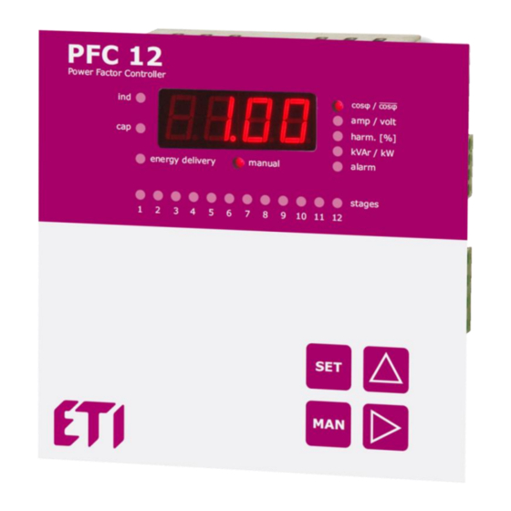
Control and signal elements Picture 1. Description of front control panel – it is ON in the case of inductive cosφ 1. LED ind – it is ON in the case of capacitive cosφ 2. LED cap – it is ON when there is power supply to electrical network 3. -
Page 4: Device Description
Device description Power factor correction regulator PFC 12 is designed for power factor control in balanced low and medium voltage system networks 50/60 Hz. PFC 12 regulators measure and display also following parameters: Parameter Display Maximum Instantaneous cosφ, average cosφ (capacitive, inductive) ●... -
Page 5: Description Of The Function
parameter St_P. Via button ▲ move to another stage and LED2 will turn ON. Repeat the same procedure the same way like for the first stage. Following the same control or setting of all stages should be done. At the end press button SET until value of power factor will appear on the display. -
Page 6: Regulator Parameter Setting
Picture 5: Connection of the PFC 12 for standard supply voltage 400 VAC Regulator parameter setting Considering various usage of regulators PFC 12, there is a number of programmable parameters. For easy start, regulator is set to default parameters, made by manufacturer. Set parameters are stated in the following table. For fast start, the parameters that should necessary be set are cosφ... - Page 7 FISt fixed capacitor stages Auto Auto / oFF / on 0° ... 330° in steps of 30° CoCo connection configuration rCPo reactive power offset for regulation 0 ... 999.9 kVAr ˉCoS on / oFF / Auto – off regulates on instant. cosφ regulation to the average power factor tACo averaging time for APFR regulation...
-
Page 8: Target Cosf Setting (Cos1, Cos2)
communication control by parity checking oFF / on /on_o CaSC ID number of parallel controller in cascade connection 0 ... 32 U_Fr grid system frequency 50 / 60Hz CodE password for access to SET mode 0000 any four digits number 0001 ... 9999 reset to the factory setting Table 4. -
Page 9: Discharging Time (Diti)
Discharging time can be set from 5 to 900 seconds. Default factory setting value is 120 seconds compatible with ETI capacitors type LPC. Default setting is optimal for capacitors with built in discharge resistors, without using extra discharge resistors or inductors. For PFC systems that have provided extra discharge resistors or inductors, which ensure quick discharge of capacitors, dit time can be much lower, but not less than 60s. -
Page 10: Reactive Power Offset (Rcpo)
Table 6. Phase shift setting for supply and measuring voltage 400 VAC 6.11. Reactive power offset (rCPo) This parameter is useful for such type of systems where there is permanent presence of inductive or capacitive reactive power offset. Typical example of this can be long lines which generates permanent and constant capacitive reactive power. Parameter rCPo is set as a real power offset present in the system. -
Page 11: Alarms
If the ot.AL alarm is enabled then alarm output is used for ventilator control. All other alarms are then only informative without feedback on the alarm output. 6.17. Configuration of RS485 communication port (PFC 12 RS) Following parameters relate to configuration of serial communication for RS485 port (MODBUS communication protocol). • Id –... -
Page 12: Displayed Values
Displayed values Monitoring features do not affect regulation process which is invisibly working all the time. Displayed value is possible to be changed at any time and LEDs on the right side of display identify type of shown value. Shown values are divided to levels so that values in one level are closely related. For switching between particular levels press button ▲... -
Page 13: Apparent Current
power factor is in inductive or capacitive area. If measuring current drops below 3 mA, controller disconnects all stages and on the display will appear " - - - - ". By button ► it is possible move to average inductive power factor indication. At first, the display will show symbol i_CoS and then after 1 second numeric value will be shown. -
Page 14: Technical Features
that caused the alarm will appear on the display and it will be followed by event value of parameter that caused an alarm action. Another pressing the button SET will cancel shown alarm. If more alarm events happened, another event symbol will appear on the display.
Need help?
Do you have a question about the PFC 12 RS and is the answer not in the manual?
Questions and answers