Table of Contents
Advertisement
Quick Links
Advertisement
Table of Contents

Related Manuals for ETI ATSC25


Summary of Contents for ETI ATSC25
- Page 1 INSTRUCTION MANUAL ATSC25 ATS Controller www.eti.eu/support...
-
Page 2: General Safety Instructions
• This manual provides instructions on safety, connections instructions on the ETI ATSC25 ATS controller • Weather the ATSC25 is sold as a loose product, as a spare, in a kit or as part of an enclosed solution or in any other... - Page 3 2. STANDARDS • As a minimum the ATSC25 comply with the following international standards: o IEC/EN 60947-6-1* o IEC/EN 60947-1 o IEC/EN 61010-2-201 o IEC/EN 61010-2-030 o IEC/EN 61010- 1 o GB/T 14048.11* o GB/T 14048.11 Annex C o EMC 60947 •...
- Page 4 ATSE formed by the association is designed for use in power systems for the safe transfer of a load supply between a normal and alternate source. When associated with ETI RTSE the changeover is done in open transition insuring full compliance with IEC 60947-6-1, GB 14048-11 and other international standards as listed.
-
Page 5: General Overview
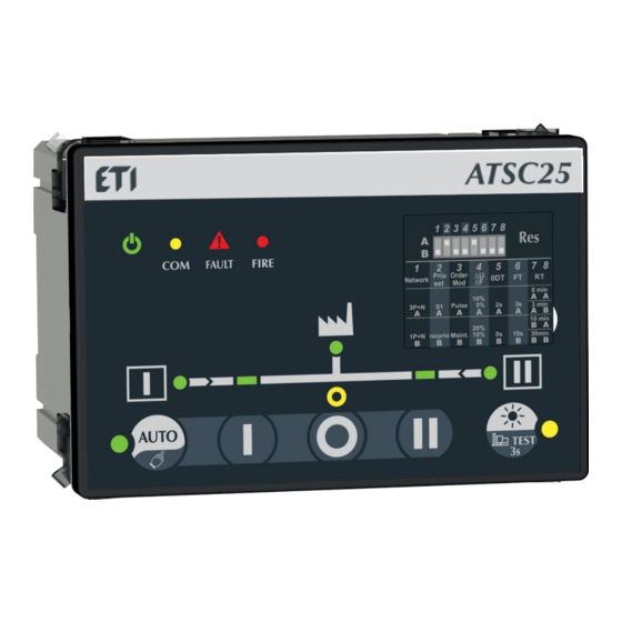
4. GENERAL OVERVIEW 4.1 Product identification 1. AUTO/Manual selector 2. Controller state LED 3. Remote position order selector 4. ATSE Synoptic 5. Test function selector 6. DIP switch programing... - Page 6 4.2 CONTROLLER HMI • 1. Source 1 availability information (Green fixed when source 1 is present and available within threshold limits, green blinking when source 1 is present but outside of threshold limits, off when under 50VAC). 2. Switch 1 LED position indication (Green fixed when in position 1). 3.
- Page 7 4.3 Environmental • The ATSC25 controllers meet the following environmental requirements: • IP Rating IP degree according to IEC 60529 • P4X on the front face when door mounted. • IP2X on the back of the controller. • IK Rating IK rating according to IEC 61010-2-201 •...
-
Page 8: Content Of Packaging
• WEEE • The ATSC25 is built in accordance with 2012/19/EU directive: • Pollution class • Pollution class II • Other compliances and marking 4.4 CONTENT OF PACKAGING The C25 packaging includes: • 1 C25 controller • 1 C25 quickstart guide •... -
Page 9: Installation
5. INSTALLATION 5.1 Product dimensions • dimensions in mm. 5.2 Mounting • • Door mounting Door cut-out of 93(+0.8) x138(+1) mm, door thickness 1.5- 3mm. Remove all connectors and clip before inserting the controller in the cut-out then fix the controller in place using all 4 fixations clips (cf. -
Page 10: Din Rail Mounting
• DIN RAIL mounting Install on IEC 60715 Standard Din RAIL. When mounting make sure both clips are pushed up, then clip on the DIN Rail. To remove from the DIN Rail, drag the two mounting clips down before removing the product. -
Page 11: Type Of Networks
In these networks, the phase must be connected to the L1 input (terminal 104 for source 1 and 204 for source 2). 3P+N: The ATSC25 is suitable for three phase with neutral networks, for with voltages within 184-300 V.a.c Ph-N and 318-520 PH-PH. - Page 12 • Metering and sensing detail In 3 phases with Neutral balanced networks, there is a risk that the loss of neutral will not be detected. CAUTION To limit this risk the Dip switch 4 (Hysteresis) can be switched to position A. (Cf chapter 7-5 programing).
- Page 13 BOTTOM 1. RTSE position feedback input 2. 24 V.d.c fire input 3. Enable control when closed / disable control when open 4. RS485 connections 5. Genset Start relay 6. RTSE position control outputs 7. Source 1 and 2 voltage inputs 8.
- Page 14 6.2 Connection diagrams with MLBS 3P/4P 250...630A • For additional connection diagrams (MLBS 4P 63...125, Contactors , etc..) see ANNEX I...
- Page 15 6.3 Terminal denomination, description and characteristics • Recom- Tightening mended torque / Denomination Terminal Description Characteristics Cable section screw type Position II order AC1 – General use – Ie: 5A , Ue: 250 V.a.c DC1 – General use – Ie: 5A , Ue: Position I order 30 V.d.c AC15 - Ie: 3A, Ue: 120 V.a.c Control signal...
- Page 16 7. ATSC25 OPERATING MODES The ATSC25 has 3 distinct working modes, the working modes are selected using the HMI button or by using the 63A/64A input. The 3 working modes are working as described below: • Auto mode In this mode the controller will automatically give orders to the RTSE connected to switch to the correct position according to the settings selected.
-
Page 17: Voltage Sensing Inputs
7.2.1 Frequency within set limits The ATSC25 will check that the frequency is within the limits configured through DIP switch 4 or through communication (cf. configuration chapter configuration). Frequency is checked on L1 only. 7.2.2... -
Page 18: Fixed Outputs
Control signal outputs are the output orders (dry contact) to the RTSE; the ATSC25 includes 3 signal outputs and a common (point powered by the user) (Terminals 17 to 14). These outputs are rated for 250 Vac, 50/60 Hz 5A general use , and 30 V.d.c 5A general use. -
Page 19: Fixed Inputs
Fixed inputs 10.4.1. Inhibit input When the contact 63A/64A is open the controller is in inhibit mode (Fault LED blinking and automatism and manual controls are deactivated). When this contact is closed the controller returns to the last working mode (either manual mode or automatic mode). When the product is delivered this input is hardwired to closed, to use the input first remove the wire 10.4.2. - Page 20 Programming The programming of the controller is done through the DIP switches available on the front HMI. WARNING Program only when in manual mode to avoid unexpected transfers or injuries. 7.5.1 Programing through DIP switch Programming through DIP switches is done using the 8 DIP switches on the front of the controller.
-
Page 21: Preventive Maintenance
8.CHARACTERISTICS Mechanical characteristics Electrical characteristics Weight 845 gr AC operating limits 184 - 300 VAC Door cutout 138 x 92 mm Optional DC supply 24 VDC -25 … +60°C Operating temperature Frequency limits 45 - 65 Hz Communications Power consumption <... -
Page 22: Troubleshooting Guide
- Verify that Communication settings are set according to your specification. - Press “RES” for 30 seconds to reset the Communication settings. - Contact ETI for other information. DIP switch parameters are not - Check if the alarm LED is blinking. - Page 23 ANNEX I Reminder C25 HMI : Source 1 availability information (Green fixed when source 1 is present and available within threshold limits, green blinking when source 1 is present but outside of threshold limits, off when under 50VAC). Switch 1 LED position indication (Green fixed when in position 1). Zero position LED indication (Yellow when in position 0).
- Page 24 11.1 LED Functioning modes LED indicator LED blinking LED ON** LED OFF* (cf HMI image) 1: Source 1 availability Source 1 present but not Source is available Source is not available available for following possible reason: -Source undervoltage / under frequency -Source overvoltage /over frequency -Phase rotation order of...
-
Page 25: Connection Diagrams
11.2 Connection diagrams 11.2.1 Connections with MLBS 4P 63...125... - Page 26 11.2.2 Connections with standard Contactors (CEM and CES)
- Page 27 11.2.3 Connections with MCCBs EB2 and MO2...
- Page 28 11.3 Phase rotation check When both sources are available the controller will check that both sources have the same phase rotation. If the two sources have different phase orders the source LED (1 & 6) will blink , the fault LED will light up and the sources will be considered as not available (switch will not transfer from the current position to the opposite source).
-
Page 29: Priority Settings
11.5.2 Cooldown timer When the switch returns in position I the Cooldown timer will start counting (Default value 180s) during the cooldown timer, the contacts will maintain the generator start signals. 11.5.3 Dead band timer ODT The dead band timer ODT can be configured using the DIP switches 5 (2s or 0s). This timer defines the time for which the switch should stay in the 0 position when transferring from one source to another. - Page 30 ATSC25 Operating sequence Controller operating sequence with source 1 priority: DPS Output operating sequence :...
- Page 31 ANNEXE II MODBUS COMMUNICATION ADDRESS AND DE- SIGNATION DETAILS All communication addresses, except communication parameters (4) are read only RO (read function 03/04). The communication protocol adopts the standard MODBUS-RTU protocol, with master-slave acknowledgment connection (half duplex). As standard the baud rate is set to 38400, parity bit to 1 (these settings can be modified through Modbus).
- Page 32 • Voltage sensing Word Dec. Address Description Unit count 10192 Source 1 L1-N voltage value 10193 Source 1 L2-N voltage value 10194 Source 1 L3-N voltage value 10195 Source 1 L-N average voltage Source 1 L1 –L2 voltage value 10196 Source 1 L2 –L3 voltage value 10197 Source 1 L3 –L1 voltage value...
- Page 33 • Maintenance Word Dec. Address Description Unit count 10126 Position I operation count in AUTO mode: 0-60 000 10128 Position II operation count in AUTO mode: 0-60 000 10130 Position I operation count in Manual mode: 0-60 000 10132 Position II operation count in Manual mode: 0-60 000 10170 -10179 Serial number 10186...
- Page 35 • Les consignes sont valables en association avec les instructions spécifiques du produit. • Tarvikuid/lisaseadmeid võib koos käesoleva tootega kasutada ainult siis, kui need on heaks kiidetud või ette nähtud ETI’i poolt. smú vykonávať iba kvalifikovaní a poverení pracovníci.
- Page 36 Mounting Hysteresis & Timers Connection with ATSC25 DIN rail mounting 10 11 1. Mounting + U/ F IEC 60715 [Hyst] DIN rail 318-520 ph-ph 318-520 ph-ph 184-300 ph-n 184-300 ph-n Vn 230 V a c L/N Un 400 V a c L/L...
Need help?
Do you have a question about the ATSC25 and is the answer not in the manual?
Questions and answers