Sign In
Upload
Download
Table of Contents
Contents
Add to my manuals
Delete from my manuals
Share
URL of this page:
HTML Link:
Bookmark this page
Add
Manual will be automatically added to "My Manuals"
Print this page
×
Bookmark added
×
Added to my manuals
Manuals
Brands
CRT Manuals
Radio
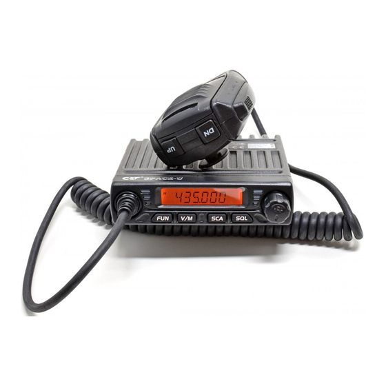
Space-U
User manual
CRT Space-U User Manual
Uhf/vhf com 400-470/136-174 mhz mobile radio, commercial programmable
Hide thumbs
1
2
3
4
5
6
7
8
9
10
11
12
13
14
15
16
17
18
19
20
21
22
23
24
25
26
27
28
29
30
31
32
33
34
35
36
37
38
Table Of Contents
39
page
of
39
Go
/
39
Contents
Table of Contents
Troubleshooting
Bookmarks
Table of Contents
Symbols Description
Storage, Transport, Using
Safety Information for User
Table of Contents
Functions & Features
Functions and Characters
Standard Accessories
Optional Accessories
Mobile Installation
Initial Installation
Install Microphone Hanger
Power Connection
Mobile Operation
Fixed Station Operation
Fuse Replacement
External Speaker
Accessories Connections
Antenna Connection
PC Connecting
Front Panel
Basic Function
Getting Acquainted
Rear Panel
Display
Amateur Transceiver Mode
Working Mode and Menu Function
Professional Transceiver Mode
Switching the Power On/Off
Power Voltage Display Function
Basic Operation
Adjusting the Volume
Switch between VFO /Channel Mode
Adjusting Frequency/Channel
Receiving
Channel Delete
Transmitting
Channel Edit
Squelch off / Squelch off Momentary
Squelch Level Setup
Frequency Scan
Shortcut Operation
Scan Skip
CTCSS/DCS Encode and Decode Setup
Function Menu
CTCSS Scan
Keypad Lockout
DCS Scan
Signaling Combination Setup
HIGH/MID/LOW Power Selection
Band-Width Selection
Busy Channel Lockout
Talk Around
Reverse Frequency
Tx off
Editing Channel Name
Offset Direction Setup
Offset Frequency Setup
Frequency Step Size Setup
Display Mode Setup
BEEP Prompt Setup
Tot(Time out Timer)
APO Setup
Reset Factory Default
Scan Dwell Time Setup
MIC Gain Setup
Power on Method Setup
Programming Software
Trouble Shooting
Maintenance
Specifications
51 Groups CTCSS Tone Frequency(Hz)
1024 Groups DCS Code
Advertisement
Quick Links
1
Functions and Characters
2
Working Mode and Menu Function
3
Basic Operation
4
Programming Software
5
Specifications
Download this manual
CRT MOBILE RADIO
USER'S MANUAL
UHF COM 400-470 Mhz
VHF COM 136-174 Mhz
Table of
Contents
Previous
Page
Next
Page
1
2
3
4
5
Advertisement
Table of Contents
Need help?
Do you have a question about the Space-U and is the answer not in the manual?
Ask a question
Questions and answers
Related Manuals for CRT Space-U
Radio CRT S MINI Manual
(3 pages)
Radio CRT SS 7900 User Manual
10 meter amateur radio (23 pages)
Radio CRT SS 6900 User Manual
10 meter radio (22 pages)
CRT SS 6900 Manual
(article)
Radio CRT SS 9900 User Manual
10 meter radio (20 pages)
Radio CRT SS 9900 User Manual
10 meter radio (21 pages)
Radio CRT Space-V User Manual
Uhf/vhf com 400-470/136-174 mhz mobile radio, commercial programmable (39 pages)
Radio CRT S 8040 Owner's Manual
Mobile cb transceiver (18 pages)
Radio CRT SS 6900V User Manual
(21 pages)
Radio CRT SS 6900V User Manual
10 meter radio (21 pages)
Radio CRT SS 7900v User Manual
10 meter amateur radio (25 pages)
Radio CRT SS 9900v User Manual
10 meter radio (31 pages)
Radio CRT Millenium User Manual
Mobile cb transceiver am- fm (21 pages)
Radio CRT Mike Owner's Manual
(24 pages)
This manual is also suitable for:
Space-v
Table of Contents
Save PDF
Print
Rename the bookmark
Delete bookmark?
Delete from my manuals?
Login
Sign In
OR
Sign in with Facebook
Sign in with Google
Upload manual
Upload from disk
Upload from URL


Need help?
Do you have a question about the Space-U and is the answer not in the manual?
Questions and answers