Elmo Rietschle G Series Operating Instructions Manual
Hide thumbs
Also See for G Series:
- Repair manual (33 pages) ,
- Operating instructions manual (48 pages)
Table of Contents
Advertisement
Quick Links
Download this manual
See also:
Repair Manual
Advertisement
Table of Contents

Related Manuals for Elmo Rietschle G Series


Summary of Contents for Elmo Rietschle G Series
- Page 1 Edition 07.2013 · 610.00280.40.000 Original operating instructions · English Operating Instructions G-BH8 2BH851 | 2BH852...
-
Page 2: Table Of Contents
Contents About this manual ................ Content of this document ............... Target group ................... Explanation of the terms and symbols ........... Changes in comparison to the previous version ......Other valid documents ..............Safety and responsibility ............. Explanation of warning signs ............Correct use of the equipment ............ - Page 3 Contents Commissioning ................Measures after a long shut-down period ........Tests during commissioning or re-commissioning ......Check the direction of rotation ............Sensors function check ..............Measure the acoustic emissions ............ Measure oscillations ............... Operation ..................Switch on ..................Switch off ..................Switch off in emergency ..............
-
Page 4: About This Manual
About this manual About this manual Content of this document These operating instructions: ▪ is part of the side-channel compressor: Series G-BH8 Types 2BH851 . . - ..- . . 2BH852 . . - ..- . . ▪... - Page 5 About this manual Symbol Explanation Disconnect prior to maintenance or repair Observe the instructions Use foot protection Use hand protection Use eye protection Use head protection Use ear protection Earth prior to use Term Explanation Plant Part provided by the user in which the side-channel com- pressor is installed.
-
Page 6: Changes In Comparison To The Previous Version
About this manual Term Explanation Integrated fre- Frequency inverter that is constructed by the manufacturer quency inverter = on the side-channel compressor. 2FC4...-1 Electrical cabinet Frequency inverter that is supplied by the manufacturer and inverter 2FC..-2 is not fitted to the side-channel compressor. Electrical cabinet A frequency inverter purchased by the operator that can be inverter, third-party... -
Page 7: Safety And Responsibility
Safety and responsibility Safety and responsibility The manufacturer is not liable for damage caused by the failure to observe these instructions and the related documents [➙ 6]. Explanation of warning signs Warning sign Explanation Danger that failure to observe the measures could lead to DANGER death or serious physical injuries. -
Page 8: Working In A Safety-Conscious Manner
Safety and responsibility ▪ Formation of condensation or liquid separation in the internal space of the G- BH8. ▪ Changes to the G-BH8 and the accessories, that have not been agreed with the manufacturer. ▪ Operation outside of the limits defined in these instructions. ▪... -
Page 9: Requirements For Personnel
Safety and responsibility Requirements for personnel 2.5.1 Staff qualifications and training All those who will work on the G-BH8 must have read and understood these and all related instructions. Personnel in training may only work on the G-BH8 under supervision of personnel who have the required knowledge. -
Page 10: Personal Protective Equipment
Safety and responsibility 2.5.2 Personal protective equipment WARNING Danger of crushing and cutting! Crushing and cutting of body parts due to sharp edges or falling parts on the open G-BH8. 1. Wear protective gloves, safety footwear and safety goggles for all assembly and disassembly, troubleshooting and maintenance work. -
Page 11: Requirements Of The Operator
Safety and responsibility Requirements of the operator WARNING Explosion and burst risk! Any machine that is operated at a pressure or speed that is beyond that which is permitted, can explode or burst and cause serious injuries due to parts flying off and suddenly ejected conveyed media. 1. -
Page 12: Product Identification
Product identification Product identification Data plate G-BH8 2BH85. . . - ..- . . No. BN XXXXXXXX XXX /YYYY IP55 IEC/EN 60034 3~ Motor TH.CL.F compressor / vacuum pump ..kW . -
Page 13: Structure
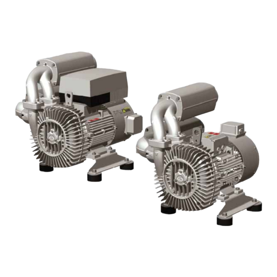
Product identification Structure Pressure side elbow Auxiliary ventilator terminal boxes Suction side elbow Asynchronous motor Silencer Motor terminal boxes Bimetal switch in the compressor housing Compressor housing Direction of conveyance arrows Rating plate Integrated frequency inverter 2FC4...-1 Assembly foot Suction side connection Spring mounts Discharge-side connection Earth connection... -
Page 14: Options
Product identification Options The G-BH8 can be delivered with the following options Electrical cabinet inverter 2FC….-2 Suction side with Y-pipe without silencer Assembly on the motor foot Suction side and/or discharge side with elbow without silencer NPT thread adapter Discharge side with hose flange without si- lencer Suction side with Y-pipe Suction side with hose flange without silencer... -
Page 15: Function Principle
Product identification Function principle With side-channel compressors, the impeller rotates contact-free in the compres- sor housing. The conveyed media is suctioned through the inlet (1) and accelerated spirally in the direction of rotation of the side channel. The conveyed media is accelerated by the centrifugal force in the radial blades in the direction of the side channel (2) inner wall, and from there is again supplied to the impeller (3). -
Page 16: Eu Declaration Of Conformity
Product identification EU declaration of conformity EU declaration of conformity Manufacturer: Gardner Denver Deutschland GmbH Industriestraße 26 97616 Bad Neustadt Germany Representative for the com- Holger Krause Industriestraße 26 pilation of technical docu- 97616 Bad Neustadt ments: Germany Designation of the machine: Vacuum pump/compressor Series G-BH8 Types... -
Page 17: Transportation And Storage
Transportation and storage Transportation and storage Unpacking and checking the condition of delivery The G-BH8 is secured onto a pallet or foot plate and protected by a cardboard box for delivery. Remove the packaging. NOTICE! First remove the transport protection on the connection open- ings before connecting the pipes and hoses. -
Page 18: Storage
Transportation and storage Storage NOTICE Mechanical damage and corrosion! Failure to adhere to the storage conditions can lead to mechanical damage and corrosion or can shorten the re-greasing interval. 1. Adhere to the storage conditions. 2. The maintenance intervals of the ball bearings (Maintenance [➙ 38]) become shorter as the time of storage increases. -
Page 19: Mounting
Mounting Mounting Measures after long-term storage Replace ball bearings and radial shaft seal When the length of storage until assembly is exceeded by 4 years for the storage conditions provided in Storage [➙ 18]. Replace the rolling bearing. Clean adjacent bearing areas for open ball bearings and re-grease. Replace and grease the radial shaft seal. -
Page 20: Set Up
Mounting Set up The G-BH8 must always be screwed to a fixed installation surface (e.g. floor) or a baseframe. Installation without spring elements is not permitted. The following assembly options are permitted: ▪ horizontally on the assembly foot (item 17, Structure [➙ 13]). ▪... -
Page 21: Fit Loose Silencer And Accessories
Mounting Fit loose silencer and accessories Fit loose silencer For G-BH8 with Y-pipe on the suction side (item 43), the silencer is enclosed separately due to technical packaging reasons and must be fitted by the op- erator. Remove transport protection. Position the silencer (item 3) on the Y-pipe with dowel pins (443) and secure using screws (444) and washers (479). - Page 22 Mounting WARNING Risk of burns due to temperatures of up to approx. 200 [392°F]! Contact with hot surfaces, pipes and hoses, can lead to burns. 1. Fit pipes and hoses with sufficient distance from highly inflammable materials (e.g. wood, plastic). 2.
-
Page 23: Electric Power Connection
Electric power connection Electric power connection General installation regulations DANGER Lethal electric shock on the housing due to the air gap being too small! Air gaps between non-insulated, voltage active components and the earth must be at least 5.5 mm [0.217 in] to one another (for a measured voltage of ≤... -
Page 24: Additional Installation Requirements For Frequency Inverters
Electric power connection The electrical equipment and control must not put the protective devices of the drive system and the motor protection (e.g. PTC resistor, bimetal switch, fre- quency inverter current limit) out of operation. When the power supply fails or surges, the control must prevent the G-BH8 from remaining in operation or starting up. -
Page 25: Prepare The Motor Terminal Box
Electric power connection ▪ The stop category and colour of the EMERGENCY OFF function must corre- spond to ISO 13850. ▪ If a risk assessment determines that the normal switch can fulfil the EMER- GENCY OFF function, this should be labelled accordingly. After an EMERGENCY OFF, start-up is only possible via a deliberate, manually- triggered procedure. -
Page 26: Connect The Frequency Inverter To The Mains
Electric power connection Connect the frequency inverter to the mains NOTICE Failure to reach the pressure values due to insufficient voltages on the mo- tor terminal board! For operation of the G-BH8 on the frequency inverter, the voltages given on the rating plate must be adhered to on the motor terminal board. - Page 27 Electric power connection Electrical cabinet inverter 2FC..-2 Open the terminal box cover of the motor (item 13, Structure [➙ 13]). Connect the electrical cabinet inverter 2FC..-2 (item 40, Options [➙ 14]) in accordance with the operating instructions 610.44526.40.000 (15-45 kW) or 610.44527.40.000 (3,0-11 kW).
- Page 28 Electric power connection Connect the electrical cabinet inverter from a third-party manufacturer Open the terminal box cover of the motor (item 13, Structure [➙ 13]). Connect electrical cabinet inverters according to the circuit diagram in the motor terminal box cover and the manufacturer's operating instructions for the frequency inverter.
-
Page 29: Connect Auxiliary Ventilator
Electric power connection Connect auxiliary ventilator DANGER Lethal electric shock on the housing due to the air gap being too small! Air gaps between non-insulated, voltage active components and the earth must be at least 5.5 mm [0.217 in] to one another (for a measured voltage of ≤... -
Page 30: Parameterize The Frequency Inverter
Electric power connection Parameterize the frequency inverter NOTICE The G-BH8 fails due to an overload of the motor! G-BH8 are not ventilators! Operation with the setting "Variable torque" or "Square characteristic" is not permitted. Always operate G-BH8 with operating mode "Constant torque" or "Linear characteristic". - Page 31 Electric power connection Electrical cabinet inverters 2FC..-2, replace ALL-Menu and Parameter 0411 settings Remove the keypad after an operating error and reconnect it. To connect, begin again with Step 1. Perform the key operations once, if not otherwise stated. Plug in the keypad and wait approx. 3 seconds. ...
-
Page 32: Commissioning
Commissioning Commissioning Measures after a long shut-down period Replace ball bearings and radial shaft seal When the time at a standstill exceeds 4 years since the last commissioning. Replace the rolling bearing. Clean adjacent bearing areas for open ball bearings and re-grease. Replace and grease the radial shaft seal. -
Page 33: Sensors Function Check
Commissioning Sensors function check Check the control for error messages by disconnecting the sensors (e.g. PTC resistor, bimetal switch). Remedy the cause of the error for any malfunctions. Measure the acoustic emissions It is necessary to measure the acoustic emissions for G-BH8 without piping or G-BH8 without silencers and with piping. -
Page 34: Operation
Operation Operation WARNING Danger of burns due to hot surfaces, pipes, hoses and media Temperatures of approx. 150 [302°F] are possible on the surfaces of the G-BH8. The outlet air can reach 200°C [392°F]. Contact with hot surfaces can lead to burns! 1. -
Page 35: Troubleshooting
Troubleshooting Troubleshooting DANGER Lethal electric shock! The frequency inverter continues to be live after the intermediate circuit voltage has been switched off, and slowly becomes de-energised. 1. After switching off, wait for at least 3 minutes. 2. Before opening the frequency inverter, ensure that it is de-energised. WARNING Danger of crushing and cutting as well as burns! Work on the G-BH8 when it is running can lead to serious injuries. - Page 36 Troubleshooting Fault Cause Corrective measure To be car- ried out by After controller release, Differential pressure does not Owner Reduce differential pres- frequency inverter goes correspond to the details on the sure. into error data plate. error message "OC3" Impeller rubs or rotor is jammed.
- Page 37 Troubleshooting Fault Cause Corrective measure To be car- ried out by Abnormal flow noises Flow rate too high. Qualified Clean pipe/hoses, use personnel pipes/hoses with a larger cross section if necessary. Silencer inserts dirty or faulty. Service* Clean the silencer inserts, check for wear and replace as necessary.
-
Page 38: Maintenance, Repairs And Spare Parts
Maintenance, repairs and spare parts Maintenance, repairs and spare parts 10.1 Maintenance DANGER Lethal electric shock! The frequency inverter continues to be live after the intermediate circuit voltage has been switched off, and slowly becomes de-energised. 1. After switching off, wait for at least 3 minutes. 2. -
Page 39: Repairs And Complaints
Maintenance, repairs and spare parts Interval Maintenance measure To be car- ried out by 20,000 h or Service* Replace the rolling bearing. 2.5 years Clean adjacent bearing areas for open ball bearings and re- grease. Grease: Klüberquiet BQH 72-102 Replace and grease the radial shaft seal. Grease: Klüberquiet BQH 72-102 Maintenance intervals have been determined for the following am- bient and operating conditions:... -
Page 40: Decommissioning
Decommissioning Decommissioning 11.1 Decommissioning DANGER Lethal electric shock! The frequency inverter continues to be live after the intermediate circuit voltage has been switched off, and slowly becomes de-energised. 1. After switching off, wait for at least 3 minutes. 2. Before opening the frequency inverter, ensure that it is de-energised. WARNING Danger of crushing and cutting as well as burns! Work on the G-BH8 when it is running can lead to serious injuries. -
Page 41: Technical Data
Technical data Technical data 12.1 Mechanical data 12.1.1 Weight Type [kg] [lbs] 2BH851 2BH852 12.1.2 Connection dimensions Fittings dimensions - internal threads The internal thread is arranged according to the order as an ISO 228-G pipe thread or as an American NPT pipe thread. The NPT thread can be recognised by the adapter (item 42, Options [➙... -
Page 42: Tightening Torque Values
Technical data 12.1.3 Tightening torque values The values apply if no other specifications are available. Steel screws Tightening torques for non-electrical connections for nuts of strength class 8 and screws of strength class 8.8 according to ISO 898-1. Thread Non-electrical Electrical* [Nm] [ft lbs]... -
Page 43: Permitted Conditions For Use
Technical data 12.2 Permitted conditions for use Any deviations from the following permissible operating conditions must be agreed with the manufacturer. 12.2.1 Installation height The maximum installation height is 1000 m ü. NHN (3280 ft above NHN) provided that no other installation height is specified on the rating plate [➙ 12] under item 12.2.2 Maximum speeds Governed speeds when using a frequency inverter... -
Page 44: Pressure Differences Acting On The Side-Channel Compressor
Technical data 12.2.5 Pressure differences acting on the side-channel compressor Maximum permissible pressure differences between the suction or pressure side and assembly environment in operation Application examples: ▪ Pressure of assembly environment ≠ atmospheric pressure ▪ Mixed operation Type Compressor operation Vacuum operation [mbar] [mbar]... -
Page 45: Speed Of Oscillation
▪ on the compressor part – vertically (compressor cover - C) – horizontally (compressor cover - D) – axially (compressor cover next to the Elmo Rietschle logo - E) 12.3 Electrical data Any deviations from the following electrical data must be agreed with the manu- facturer. -
Page 46: Acoustic Emissions
Technical data 12.5 Acoustic emissions Measured area sound pressure level L in accordance with ISO 3744, measured at a distance of 1 m for 70% Δp and connected supply lines, tolerance ±3 dB(A). Type Compressor operation Vacuum operation [dB(A)] [dB(A)] 167 Hz 235 Hz 167 Hz... - Page 47 Technical data © Gardner Denver Deutschland GmbH 07.2013 · 610.00280.40.000...
- Page 48 Gardner Denver Deutschland GmbH Industriestraße 26 97616 Bad Neustadt · Deutschland Tel. +49 9771 6888-0 Fax +49 9771 6888-4000 Elmo Rietschle is a brand of Gardner Denver‘s Industrial Products Group and part of Blower Operations.
Need help?
Do you have a question about the G Series and is the answer not in the manual?
Questions and answers