
Related Manuals for Elmo Rietschle F-CEVF Series


Summary of Contents for Elmo Rietschle F-CEVF Series
- Page 1 Edition 02.2017 · 610.00181.40.000 Original operating instructions · English Operating instructions F-CEVF 3718-3(29)(A002)(31)(45)(55)(90) F-CEVF 3718-4(29)(A002)
-
Page 2: Table Of Contents
Contents About this manual ................ Content of this document ............... Target group ................... Explanation of the terms and symbols ........... Changes in comparison to the previous version ......Safety and responsibility ............. Explanation of warning signs ............Correct use of the equipment ............Unauthorised operation .............. - Page 3 Contents Technical data ................12.1 Mechanical data ................12.1.1 Weight .................... 12.1.2 Fitting dimensions for hose ............12.2 Permitted conditions for use ............12.2.1 Installation height ................12.2.2 Rotational speeds ................12.2.3 Temperatures ................. 12.2.4 Pressure differences ............... 12.2.5 Relative humidity ................12.2.6 Minimum distances ................
-
Page 4: About This Manual
About this manual About this manual Content of this document These operating instructions: ▪ Is a component of the suction blower: Series F-CEVF Types F-CEVF 3718-3(29) F-CEVF 3718-4(29) F-CEVF 3718-3(A002) F-CEVF 3718-4(A002) F-CEVF 3718-3(31) F-CEVF 3718-3(45) F-CEVF 3718-3(55) F-CEVF 3718-3(90) ▪... - Page 5 About this manual Symbol Explanation F-CEVF can start without warning Electrical voltage warning Hot surface warning Disconnect prior to maintenance or repair Earth prior to use Observe the instructions Term Explanation Plant Part provided by the user in which the F-CEVF is installed. F-CEVF = Suction Ready-to-connect blower for suction operations, for high-volume flow rates with blower...
-
Page 6: Changes In Comparison To The Previous Version
About this manual Changes in comparison to the previous version Changes compared with version 01.2016 ▪ Explanation of the terms and symbols [ ▪ Safety and responsibility [ ▪ Rating plate [ ▪ Design of the machine [ ▪ EC/EU declaration of conformity [ ▪... -
Page 7: Safety And Responsibility
Safety and responsibility Safety and responsibility The manufacturer is not liable for damage caused by the failure to observe these instructions and the related documents. Explanation of warning signs Warning sign Explanation Danger that failure to observe the measures could lead to death or serious phys- ical injuries. -
Page 8: Unauthorised Operation
Safety and responsibility Unauthorised operation It is forbidden to: ▪ Operating in a potentially explosive area (ATEX). ▪ Connecting to a potentially explosive area (ATEX). ▪ Transporting explosive, flammable, aggressive, unstable, oxydative or poison- ous materials. ▪ Using non-commercial facilities without making adjustments for the additional requirements. -
Page 9: Requirements For Personnel
Safety and responsibility Requirements for personnel 2.5.1 Staff qualifications and training All those who will work on the F-CEVF must have read and understood these in- structions and the related documents. Personnel in training may only work on the F-CEVF under supervision of personnel who have the required knowledge. -
Page 10: Personal Protective Equipment
Safety and responsibility 2.5.2 Personal protective equipment WARNING Danger of crushing and cutting! Crushing and cutting of body parts due to sharp edges or falling parts on the open F-CEVF. 1. Wear protective gloves, safety footwear and safety goggles for all assembly and disassembly, troubleshooting and maintenance work. -
Page 11: Requirements Of The Operator
Safety and responsibility Requirements of the operator WARNING Destruction due to bursting or exploding! Any machine that is operated at a pressure or speed that is beyond that which is permitted can explode or burst and cause serious injuries due to parts flying off and conveyed media being suddenly ejected. -
Page 12: Product Identification
Product identification Product identification Rating plate Rating plate of the compressor (item 2000, [ 13]) Rating plate of the motor (Pos. 2000, [ 13]) Series Pressure differences Type values with a negative sign apply to vacuum- ing and vacuum operations Serial number/year of manufacture Volume flow Machine type, protection class, thermal class... -
Page 13: Design Of The Machine
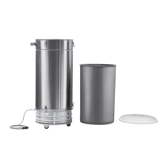
Product identification Design of the machine 0001 Drive motor 0409 Quick-release clamp (on top) 0020 Filter body 0409 Quick-release clamp (on bottom) 0040 Connection cable 0500 Motor protection circuit breaker 0042 Junction box 2000 Rating plate 0062 Feet 5190 Adhesive label with direction of rotation arrow 0182 Castors N1.0 Gas inlet... -
Page 14: Function Principle
Product identification Function principle The F-CEVF suction blower is a multi-stage blower that works according to the dynamic compressing principle and operates with a non-contact rotating impeller. It has a gas inlet (item N1.0, [ 13]). The drive and the fan form a single unit. A shaft seal is arranged between the storage chamber and the compression cham- ber. -
Page 15: Ec/Eu Declaration Of Conformity
Product identification EC/EU declaration of conformity Manufacturer: Gardner Denver Deutschland GmbH Industriestraße 26, 97616 Bad Neustadt, Germany Holger Krause, Gardner Denver Deutschland GmbH Representative for the Industriestraße 26, 97616 Bad Neustadt, Germany compilation of technical documents: Vacuum Pump Designation of the ma- chine: Series F-CEVF... -
Page 16: Transportation And Storage
Transportation and storage Transportation and storage Unpacking and checking the condition of delivery The F-CEVF is secured onto a pallet and protected by a cardboard box for deliv- ery. Remove the packaging. NOTICE! First remove the transport protection on the connection open- ings before connecting the pipes and hoses. -
Page 17: Storage
Transportation and storage Storage NOTICE Mechanical damage and corrosion! Failure to adhere to the storage conditions can lead to mechanical damage and corrosion. 1. Seal all openings so that no dirt or solid particles can enter. 2. Avoid storage for more than 6 months. 3. -
Page 18: Mounting
Mounting Mounting Measures after long-term storage Measuring the motor insulation resistance Measure the insulation resistance of the motor at 500V DC voltage between the conductors of the main circuit and protective conductive system. Value ≥1 MΩ: no measures necessary. ... -
Page 19: Connecting Pipelines And Hoses
Mounting Connecting pipelines and hoses WARNING Risk of injury due to prohibited system-side loads! Suddenly ejected conveyed media such as impurities and solid particles or pressure surges can lead to serious injuries. 1. Dimension pipes and hoses, securing elements, fittings and containers suffi- ciently and align them to the maximum pressures. -
Page 20: Electric Power Connection
Electric power connection Electric power connection General installation regulations NOTICE Destruction of the drive! Incorrect operation or incorrect control can destroy the drive. 1. The F-CEVF is equipped with an asynchronous motor. 2. Operating on a grid with a non-earthed start point is not permitted. The electrical installation must correctly fulfil the requirements of IEC 60204-1, IEC 60204-11 and IEC 61010-1 in accordance with the ambient and operating conditions. -
Page 21: Controls
Electric power connection Controls Controls and instruments must be constructed and arranged in such a way that: ▪ They are easily visible and accessible, and can also be operated without ex- cessive effort. ▪ The operator understands the functions. ▪ Operating faults are prevented. A control system must correspond to IS ©... -
Page 22: Connect The Motor To The Mains
Electric power connection Connect the motor to the mains F-CEVF with junction box (item 0042, [ 13]) or motor protection circuit breaker (item 0500, [ 13]) Open junction box cover or motor protection circuit breaker. Open access points for cable glands. Screw in or insert cable glands and secure with locknut. -
Page 23: Commissioning
Commissioning Commissioning Measures after a long shut-down period Measuring the motor insulation resistance Measure the insulation resistance of the motor at 500V DC voltage between the conductors of the main circuit and protective conductive system. Value ≥1 MΩ: no measures necessary. ... -
Page 24: Operation
Operation Operation When operating the F-CEVF, comply with the Permitted conditions for use [ 28]. Switch on If fitted, open the shut-off devices in the suction line. Switch on current supply. The F-CEVF begins to suction conveyed media. Switch off Switch off current supply. -
Page 25: Troubleshooting
Troubleshooting Troubleshooting Voiding of the warranty! The opening of the F-CEVF by the operator within the warranty period can lead to voiding of the warranty. Fault Cause Corrective measure To be car- ried out by F-CEVF does not start The power supply of the F-CEVF Correct the break in fuses, Electrician up and does not make... -
Page 26: Maintenance
Maintenance Maintenance Maintenance For the safe operation of the F-CEVF, the following maintenance intervals are rec- ommended. They are dependent on the operating conditions and must be adjust- ed by the user as necessary. Maintenance interval Maintenance measure To be car- ried out by Depending on the con- Checking and emptying the filter bags / filter cartridge... -
Page 27: Decommissioning
Decommissioning Decommissioning 11.1 Decommissioning The F-CEVF can remain in the unit or be dismantled for storage. Disconnect the F-CEVF from the power supply. Depressurise the pipes. 11.2 Disassembly Disconnect the F-CEVF from all electrical connections. Dismantle the piping and hoses. Close connections that are open. - Page 28 Technical data Technical data 12.1 Mechanical data 12.1.1 Weight Type [kg] [lbs] F-CEVF 3718-3(29)(A002) (45) 1.1 kW F-CEVF 3718-3(45) 1.3 kW F-CEVF 3718-3(31)(55)(90) 2.2 kW F-CEVF 3718-3(55) 1.5 kW, KD version F-CEVF 3718-3(29)(A002) 2.6 kW F-CEVF 3718-4(29)(A002) 1.5 kW 12.1.2 Fitting dimensions for hose Connection dimensions for gas inlet (item N1.0, [ 13])
- Page 29 Technical data 12.2.4 Pressure differences Pressure differences generated in operation by F-CEVF Vacuum mode, maximum [mbar] Item p The pressure differences specified on the rating plate serve as reference condi- tions [ 5] and have a tolerance of ±10%. Loss of piping must be considered. 12.2.5 Relative humidity Ambient relative humidity...
- Page 30 Technical data 12.4 Acoustic emissions Emission sound pressure level L according to noise test code ISO 2151 with reference to the basic standard ISO 3744. Measured at a distance of 1 m for 70% Δp and connected supply lines, tolerance ±3 dB(A). Type 50 Hz 60 Hz...
Need help?
Do you have a question about the F-CEVF Series and is the answer not in the manual?
Questions and answers