Table of Contents
Advertisement
Available languages
Available languages
Quick Links
Advertisement
Chapters
Table of Contents

Related Manuals for Elmo Rietschle S-VSI 301


Summary of Contents for Elmo Rietschle S-VSI 301
- Page 1 Edition: 1.0 · 5.9.2018 · BA 834-DE Original Betriebsanleitung S-VSI 301 Vakuumpumpe S-Serie S-Series Schraube Screw Prematic AG, Märwilerstrasse 43, 9556 Affeltrangen www.prematic.ch Tel. 071 918 60 60, Mail: v-g@prematic.ch...
-
Page 2: Table Of Contents
Inhaltsverzeichnis Inhaltsverzeichnis Vorwort ..............Grundsätze . - Page 3 Inhaltsverzeichnis Energieversorgung anschließen ..........5.6.1 Motor anschließen .
-
Page 4: Vorwort
Vorwort Vorwort Grundsätze Diese Betriebsanleitung: • ist ein Teil von folgenden Schrauben-Vakuumpumpen der Typen S-VSI 301 • beschreibt den sicheren und sachgemäßen Einsatz in allen Lebensphasen • muss am Einsatzort verfügbar sein. Zielgruppe Zielgruppe dieser Anleitung ist ein technisch geschultes Fachpersonal. -
Page 5: Symbole Und Bedeutung
Vorwort Symbole und Bedeutung Symbol Erklärung Handlungsanweisung, Maßnahme Ø a), b),... Mehrschrittige Handlungsanweisung Ergebnis Verweis Warnzeichen Beachten Sie alle Sicherheitshinweise mit diesem Symbol, um Verletzun- gen oder Tod zu vermeiden. Warnt vor potenzieller Verletzungsgefahr Warnt vor elektrischer Spannung Warnt vor schwebenden Lasten Warnt vor heißer Oberfläche Warnt vor automatischem oder unerwartetem Anlauf der Maschine Gebotszeichen... -
Page 6: Fachbegriffe Und Bedeutung
Vorwort Fachbegriffe und Bedeutung Begriff Erklärung Maschine Anschlussfertige Kombination aus Pumpe und Motor Motor Antriebsmotor der Pumpe Vakuumpumpe Maschine zur Erzeugung eines Unterdrucks (Vakuum) Schraube Konstruktions- bzw. Wirkprinzip der Maschine Volumenstrom einer Vakuumpumpe bezogen auf den Zustand im Saugvermögen Sauganschluss Enddruck (abs.) Das maximale Vakuum, das eine Pumpe bei geschlossener Ansaugöff- nung erreicht, als Absolutdruck angegeben... -
Page 7: Sicherheit
Sicherheit Sicherheit Der Hersteller haftet nicht für Schäden aufgrund Nichtbeachtung der Gesamtdokumentation. Kennzeichnung von Warnhinweisen Warnhinweis Gefahrenstufe Folgen bei Nichtbeachtung GEFAHR unmittelbar drohende Gefahr Tod, schwere Körperverletzung WARNUNG mögliche drohende Gefahr Tod, schwere Körperverletzung VORSICHT mögliche gefährliche Situation Leichte Körperverletzung ACHTUNG mögliche gefährliche Situation Sachschaden... -
Page 8: Unzulässige Betriebsweisen
Sicherheit Unzulässige Betriebsweisen • absaugen, fördern und verdichten von explosiven, brennbaren, aggressiven oder giftigen Medien, z. B. Staub gemäß ATEX Zone 20-22, Lösungsmittel sowie gasförmiger Sauerstoff und andere Oxidationsmit- tel, Flüssigkeiten oder Feststoffe • der Einsatz der Maschine in nicht gewerblichen Anlagen, sofern anlagenseitig nicht die notwendigen Vor- kehrungen und Schutzmaßnahmen getroffen werden •... -
Page 9: Sicherheitshinweise Für Aufstellung, Inbetriebnahme Und Wartung
Sicherheit Sicherheitshinweise für Aufstellung, Inbetriebnahme und Wartung • Der Betreiber sorgt dafür, dass alle Arbeiten für die Aufstellung, Inbetriebnahme und Wartung von auto- risiertem und qualifiziertem Fachpersonal ausgeführt werden, welches sich durch eingehendes Studium der Betriebsanleitung ausreichend informiert hat • Arbeiten an der Maschine nur im Stillstand und gegen Wiedereinschalten gesichert ausführen •... -
Page 10: Transport, Lagerung Und Entsorgung
Transport, Lagerung und Entsorgung Transport, Lagerung und Entsorgung Transportieren 3.1.1 Auspacken und Lieferzustand prüfen a) Maschine beim Empfang auspacken und auf Transportschäden prüfen. b) Transportschäden sofort dem Hersteller melden. c) Verpackungsmaterial gemäß örtlich geltender Vorschriften entsorgen. 3.1.2 Anheben und Transportieren Ringschrauben Abb. -
Page 11: Lagern
Transport, Lagerung und Entsorgung Lagern ACHTUNG Sachschaden durch unsachgemäße Lagerung! Durch unsachgemäße Lagerung kann die Maschine beschädigt werden. Sicherstellen, dass der Lagerraum folgende Bedingungen erfüllt: Ø staubfrei Ø erschütterungsfrei 3.2.1 Umgebungsbedingungen beim Lagern Umgebungsbedingung Wert Relative Feuchte 0 % bis 80 % Lagertemperatur -10 °C bis +60 °C Die Maschine ist in trockener Umgebung mit normaler Luftfeuchtigkeit zu lagern. -
Page 12: Produktübersicht Und Funktion
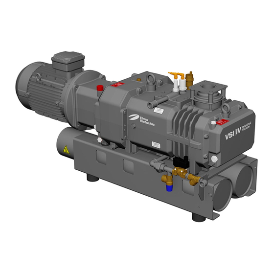
K, K Ölablassstelle Schmutzfänger Ölempfehlungsschild Kondensatablass G Datenschild Ausblasschalldämpfer Drehrichtungsschild Abb. 2 Vakuumpumpe S-VSI 301 mit Durchlaufkühlung www.gd-elmorietschle.com © Gardner Denver Schopfheim GmbH, Gardner Denver Deutschland GmbH Prematic AG, Märwilerstrasse 43, 9556 Affeltrangen www.prematic.ch Tel. 071 918 60 60, Mail: v-g@prematic.ch... -
Page 13: Produktübersicht Umlaufkühlung (Wasser-Luft-Wärmetauscher)
Kondensatablass G heiße Oberflächen > 70 ° C Ausblasschalldämpfer Wärmetauscher Abb. 3 Vakuumpumpe S-VSI 301 mit Umlaufkühlung www.gd-elmorietschle.com © Gardner Denver Schopfheim GmbH, Gardner Denver Deutschland GmbH Prematic AG, Märwilerstrasse 43, 9556 Affeltrangen www.prematic.ch Tel. 071 918 60 60, Mail: v-g@prematic.ch... -
Page 14: Datenschild
Produktübersicht und Funktion Datenschild Typ / Baugröße (mechanische Variante) Drehzahl 50 Hz / 60 Hz Seriennummer Motorleistung 50 Hz / 60 Hz Baujahr Betriebsart Data Matrix Barcode Saugvermögen Artikel-Nr. Enddruck (abs.) Abb. -
Page 15: Einsatzbereiche
ACHTUNG Sachschaden durch nicht bestimmungsgemäßen Betrieb! Durch falsche Betriebsart kann die Maschine beschädigt werden. Ø Die Schrauben-Vakuumpumpe S-VSI 301 mit 5,5 kW Motor darf nur im Dauerbetrieb S1 betrieben werden. Zubehör Folgendes Zubehör ist optional und auf Anfrage bei Gardner Denver erhältlich. -
Page 16: Kühlung Der Maschine
Produktübersicht und Funktion Kühlung der Maschine 4.7.1 Durchlaufkühlung (Standard) Kühlwassereintritt G Sicherheitsventil Kühlwasseraustritt G Wasserstandswächter Schnellentlüftungsventil Magnetventil Temperaturwächter Schmutzfänger Abb. 5 Durchlaufkühlung Bei der Durchlaufkühlung strömt Wasser kontinuierlich durch den Hohlraum des doppelwandigen Verdichtergehäuses. Aus Sicherheitsgründen ist das Kühlsystem mit einem Magnetventil, Temperaturwächter und einem Sicher- heitsventil ausgestattet. -
Page 17: Umlaufkühlung (Wasser-Luft-Wärmetauscher)
Produktübersicht und Funktion 4.7.2 Umlaufkühlung (Wasser-Luft-Wärmetauscher) Schnellentlüftungsventil Umwälzpumpe (IP 42) Temperaturwächter Manometer Wasserstandswächter Druckausgleichsbehälter Lüfter (IP 44) Wärmetauscher Abb. 6 Umlaufkühlung Bei der Umlaufkühlung wird der Verdichter einmalig mit einem Wasser-Glysantin-Gemisch befüllt. Dieses wird mit Hilfe einer Umwälzpumpe kontinuierlich durch den Verdichter und den Wärmetauscher gepumpt. Der Wärmetauscher ist luftgekühlt (Ventilator). -
Page 18: Aufstellung
Aufstellung Aufstellung Aufstellung vorbereiten Stellen Sie folgende Bedingungen sicher: • Maschine von allen Seiten frei zugänglich • Lüftungsgitter und -öffnungen nicht verschließen • genügend Raum für Ein-/Ausbau der Rohrleitungen sowie Wartungsarbeiten, insbesondere für Aus-/Ein- bau der Maschine • keine Einwirkung von Fremdschwingungen •... -
Page 19: Rohrleitungen Anschließen
Aufstellung Rohrleitungen anschließen ACHTUNG Sachschaden durch zu hohe Kräfte und Drehmomente der Rohrleitungen auf das Aggregat! Durch zu hohe Kräfte und Drehmomente während der Installation und des Betriebs kann die Maschine beschädigt werden. Ø Rohrleitungen nur von Hand einschrauben. Ø Verwenden Sie gegebenenfalls flexible Verbindungen. VORSICHT Verletzungsgefahr durch verschlossene Abluftöffnung! Durch verschlossene, eingeengte oder abgedeckte Abluftöffnungen wird der Gegen-... -
Page 20: Kühlwasseranschluss Bei Durchlaufkühlung
Aufstellung 5.4.1 Kühlwasseranschluss bei Durchlaufkühlung VORSICHT Verletzungsgefahr durch Stürzen! Durch auslaufende Flüssigkeiten kann der Boden rutschig werden und Personen können stürzen. Ø Pumpe auf Kühlwasserverlust und Leckage prüfen. Ø Rutschfeste Schuhe tragen. ACHTUNG Sachschaden durch falsches Kühlmittel! Schmutzpartikel und aggressives Wasser können zu Fehlfunktion bzw. zu vorzeitigem Verschleiß... -
Page 21: Kühlwasseranschluss Bei Umlaufkühlung
Aufstellung 5.4.2 Kühlwasseranschluss bei Umlaufkühlung Die Pumpen mit Wasser-Luft-Wärmetauscher sind bei der Lieferung bereits mit Kühlwasser befüllt (Was- ser-Glysantin-Gemisch im Verhältnis 70:30). a) Füllstand des Kühlwasser am Manometer (Abb. 3/W ) kontrollieren. Fülldruck: min. 0,6 bar (g), max. 1,2 bar (g) b) Gegebenenfalls Kühlwasser nachfüllen. Nachfüllen: siehe Kapitel 7.2.3, Seite 32 WARNUNG Gesundheitsgefahr durch unsachgemäße Umgang mit Frostschutzmitteln! -
Page 22: Energieversorgung Anschließen
Aufstellung Energieversorgung anschließen GEFAHR Lebensgefahr durch nicht fachgerechte elektrische Installation! Eine nicht fachgerechte oder fehlerhaft ausgeführte elektrische Installation kann zu schweren Verletzungen bis zum Tod führen. Die gesamte elektrische Anlage kann zer- stört werden. Ø Die elektrische Installation darf nur von einer Elektrofachkraft unter Einhaltung der EN 60204 vorgenommen werden. -
Page 23: Inbetriebnahme Und Außerbetriebnahme
Inbetriebnahme und Außerbetriebnahme Inbetriebnahme und Außerbetriebnahme Inbetriebnahme WARNUNG Verletzungsgefahr durch unsachgemäßen Betrieb! Unsachgemäßer Betrieb der Maschine kann zu schweren oder tödlichen Verletzungen führen. Ø Unbedingt die Sicherheitshinweise beachten. Auch die Sicherheitshinweise in Kapi- tel 2 beachten. VORSICHT Verletzungsgefahr durch heiße Oberflächen! Im betriebswarmen Zustand können die Oberflächentemperaturen an den Bauteilen über 70 °C ansteigen. -
Page 24: Drehrichtung Prüfen
Inbetriebnahme und Außerbetriebnahme 6.1.1 Drehrichtung prüfen VORSICHT Verletzungsgefahr durch falsche Drehrichtung! Längerer Rückwärtslauf kann zu Verletzungen durch Ansaugen führen und Beschädi- gungen an der Maschine verursachen. Ø Verwenden Sie einen Drehfeldanzeiger zur Prüfung der Drehrichtung (Linksdrehfeld). Ø Halten Sie 1 m Abstand zu Druck- und Sauganschlüssen. Die vorgesehene Drehrichtung der Antriebswelle ist durch den Drehrichtungspfeil (Abb. -
Page 25: Außerbetriebnahme/ Einlagern
Inbetriebnahme und Außerbetriebnahme Außerbetriebnahme/ Einlagern Maschine stilllegen a) Maschine ausschalten. b) Falls vorhanden, Absperrorgan in Saug- und Druckleitung schließen. c) Maschine von der Spannungsquelle trennen. d) Maschine druckentlasten: Rohrleitungen langsam öffnen. Druck baut sich langsam ab. e) Rohrleitungen und Schläuche entfernen. Anschlüsse für Saug- und Druckstutzen mittels Klebefolie verschließen. -
Page 26: Wartung Und Instandsetzung
Wartung und Instandsetzung Wartung und Instandsetzung GEFAHR Lebensgefahr durch Berührung spannungsführender Teile! Das Berühren von spannungsführenden Teilen kann zu schweren Verletzungen bis zum Tod führen. Ø Vor allen Wartungsarbeiten Maschine durch Betätigen des Hauptschalters oder Ziehen des Netzsteckers von der Spannungsversorgung trennen und gegen Wieder- einschalten sichern. -
Page 27: Wartungstätigkeiten
Wartung und Instandsetzung Wartungstätigkeiten Intervall Wartungsmaßnahmen Kapitel monatlich Verrohrung und Verschraubungen auf Undichtigkeiten und — festen Sitz prüfen und ggf. neu abdichten/ nachziehen. Klemmenkasten und Kabeleinführungsöffnungen auf Undich- — tigkeiten prüfen und ggf. neu abdichten. Kühlrippen der Maschine und des Motor reinigen. —... - Page 28 Wartung und Instandsetzung 7.2.1 Ölwechsel Öleinfüllstelle mit Entlüftungsschraube K, K Ölablassstelle Öleinfüllstelle Ölempfehlungsschild I, I Ölschauglas Abb. 9 Ölwechsel VORSICHT Verletzungsgefahr durch heiße Oberflächen und Schmiermittel! Bei Wartungsarbeiten besteht Verbrennungsgefahr an heißen Bauteilen und Schmiermit- teln der Maschine. Dies kann zu Verbrennungen führen. Ø...
- Page 29 Ölwechsel nach je 7.500 Betriebsstunden durchführen. c) Zum Nachfüllen von Öl muss die Maschine abgeschaltet und auf Atmosphärendruck geflutet werden. Als Betriebsmittel empfehlen wir die Verwendung der Elmo Rietschle Öle (siehe auch Ölempfehlungsschild (Abb. 9/M)). Elmo Rietschle Ölsorten: GEAR-LUBE 150 – Synthetiköl, hoch belastbar bei hoher Alterungsbeständigkeit und exzellentem Verschleißschutz...
-
Page 30: Luftfilter
Wartung und Instandsetzung 7.2.2 Luftfilter Saugflansch Schrauben Siebfilter Gasballastventil (Zubehör bei IV-Variante) Abb. 10 Luftfilter WARNUNG Verletzungsgefahr durch rotierende Teile! Durch Ausbau des Saugflansches besteht beim Hineinfassen Verletzungsgefahr an rotierenden Teilen. Ø Vor dem Ausbau des Saugflansches Pumpe von der Spannungsversorgung trennen und gegen Wiedereinschalten sichern. - Page 31 Wartung und Instandsetzung ACHTUNG Sachschaden durch ungenügende Wartung des Luftfilters! Durch verschmutzten Luftfilter und ungenügende Wartung vermindert sich die Leistung der Maschine. Dies kann auch zur Beschädigung der Maschine führen. Ø Siebfilter regelmäßig reinigen. Ø Stark verschmutzte oder beschädigte Siebfilter ersetzen. Filter-Ansaugluft: Der Siebfilter (Abb.
-
Page 32: Kühlung
Wartung und Instandsetzung 7.2.3 Kühlung Manometer Entlüftungsschraube (Wärmetauscher) Druckausgleichsbehälter Entlüftungsschraube (Kühlwasserkreislauf) Kugelhahn Wärmetauscher Abb. 12 Umlaufkühlung Kühlwasserkreislauf und Zuleitungen monatlich überprüfen. Durchlaufkühlung Je nach Verschmutzung des Kühlwassers ist nach angemessenen Zeitabständen der Schmutzfänger (Abb. 5/U ) zu warten. Dazu Verschlussschraube öffnen und eingebautes Sieb reinigen. Umlaufkühlung WARNUNG Verletzungsgefahr beim Umgang mit Druckluft! - Page 33 Wartung und Instandsetzung Kühlwasser nachfüllen: a) Entlüftungsschraube (Abb. 12/W ) am Kühlkreislauf lösen. b) Kühlkreislauf mit Wasser-Glysantin-Gemisch (Verhältnis 70:30) am Kugelhahn (Abb. 12/W ) befüllen, bis das Kühlwasser an der Entlüftungsschraube (Abb. 12/W ) austritt. Entlüftungsschraube (Abb. 12/W ) verschließen c) Kühlkreislauf bis zu einem Druck von max.
-
Page 34: Kupplung
Wartung und Instandsetzung 7.2.4 Kupplung Kupplungs-Zahnkranz motorseitige Kupplungshälfte Motor Schrauben Motorflanschgehäuse Abb. 13 Kupplung ACHTUNG Sachschaden durch defekten Kupplungs-Zahnkranz! Defekte Zahnkränze können zum Bruch der Rotorwelle und zum Ausfall der Maschine führen. Ø Kupplungszahn regelmäßig auf Verschleiß prüfen. ACHTUNG Sachschaden durch häufigen Anlauf und hohe Umgebungstemperatur! Durch häufigen Anlauf und hohe Umgebungstemperatur wird die Lebensdauer des Zahnkranzes verkürzt. -
Page 35: Reparatur/ Service
Verletzungsgefahr durch gesundheitsgefährdende Schadstoffe! Durch einsatzbedingte Kontaminierung mit Schadstoffen und Betriebsmitteln besteht erhebliche Gesundheitsgefahr für das Reparaturpersonal. ¾ Jeder Maschine, die zur Inspektion, Wartung oder Reparatur an eine Elmo Rietschle Service-Stelle geschickt wird, muss eine vollständig ausgefüllte und unterschriebene Unbedenklichkeitserklärung beigefügt werden. -
Page 36: Ersatzteile
Ø Verwenden Sie ausschließlich Original-Ersatzteile oder vom Hersteller genehmigte Teile. Ø Die Verwendung anderer Teile hebt die Haftung bzw. Gewährleistung für die daraus entstehenden Folgen auf. Ersatzteilbestellung gemäß: • Ersatzteilliste: E 834 ¦ S-VSI 301 • Download der PDF-Datei: http://www.gd-elmorietschle.com ¦ Downloads ¦ Produkt Dokumente ¦ S-Series ¦ Datenblätter, Anleitungen und Servicedokumente ¦ ... -
Page 37: Störungen: Ursachen Und Beseitigung
Service Geräusch Bei weiteren oder nicht behebbaren Störungen wenden Sie sich an den Elmo Rietschle Service. www.gd-elmorietschle.com © Gardner Denver Schopfheim GmbH, Gardner Denver Deutschland GmbH Prematic AG, Märwilerstrasse 43, 9556 Affeltrangen www.prematic.ch Tel. 071 918 60 60, Mail: v-g@prematic.ch... -
Page 38: Technische Daten
Technische Daten Technische Daten Durchlaufkühlung (Standard) S-VSI 5,5 kW 7,5 kW Schalldruckpegel (max.) 50 Hz dB(A) 200 mbar (abs.) ¦ 0,08 mbar (abs.) 60 Hz Toleranz ± 3 dB(A) EN ISO 3744, 50 Hz Schallleistungspegel dB(A) 60 Hz Gewicht * Länge * 1246 1249... -
Page 39: Umlaufkühlung (Wasser-Luft-Wärmetauscher)
Weitere technische Daten entnehmen Sie bitte den Datenblättern D 834 und D 834-UK • Download der PDF-Datei: D 834 ¦ S-VSI 301 (Standard) D 834-UK ¦ S-VSI 301 (Umlaufkühlung) • Download der PDF-Datei: http://www.gd-elmorietschle.com ¦ Downloads ¦ Produkt Dokumente ¦ S-Series ¦ Datenblätter, Anleitungen und Servicedokumente ¦ ... - Page 40 Prematic AG, Märwilerstrasse 43, 9556 Affeltrangen www.prematic.ch Tel. 071 918 60 60, Mail: v-g@prematic.ch...
- Page 41 Elmo Rietschle is a brand of Gardner Denver‘s Industrial Products Division and part of Blower Operations. Prematic AG, Märwilerstrasse 43, 9556 Affeltrangen www.prematic.ch Tel. 071 918 60 60, Mail: v-g@prematic.ch...
- Page 42 Edition: 1.1 · 11.6.2019 · BA 834-EN Translation of the original Operating Instructions Operating Instructions S-VSI 301 Vacuum pump S-Serie S Series Schraube Screw Prematic AG, Märwilerstrasse 43, 9556 Affeltrangen www.prematic.ch Tel. 071 918 60 60, Mail: v-g@prematic.ch...
- Page 43 Table of contents Table of contents Foreword ..............Principles .
- Page 44 Table of contents Check lubricating oil ............Connect to the energy supply network .
-
Page 45: Foreword
Principles These Operating Instructions: • Are a part of the following screw vacuum pumps of the types S-VSI 301 • Describes how to use them safely and properly in all life phases • Must be available where the equipment is used. -
Page 46: Symbols And Meaning
Preface Symbols and meaning Symbol Explanation Instructions, action Ø a), b),... Instructions in several steps Results Reference Warning signs Obey all safety instructions with this symbol in order to avoid injury or death. Warns of potential risk of injury Warns of electrical voltage Warns of suspended loads Warns of hot surface Warns of automatic or unexpected start-up of the machine... -
Page 47: Specialist Terms And Meaning
Preface Specialist terms and meaning Term Explanation Machine Pump and motor combination ready for connection Motor Pump drive motor Vacuum pump Machine for creating underpressure (vacuum) Screw Design or operating principle of the machine Suction capacity Vacuum pump volume flow related to the condition in the inlet connection Final pressure (abs.) The maximum vacuum that a pump reaches when the inlet opening is closed, indicated as absolute pressure... -
Page 48: Safety
Safety Safety The manufacturer is not responsible for damage due to non-observance of the whole documentation. Labelling of warnings Consequences of Warning Danger level non-observance DANGER Imminent danger Death, severe bodily injury WARNING Possible imminent danger Death, severe bodily injury CAUTION Possible hazardous situation Slight bodily injury... -
Page 49: Inadmissible Operating Modes
Safety Inadmissible operating modes • Extracting, conveying and compressing explosive, inflammable, aggressive or poisonous media, e.g. dust as per ATEX zone 20-22, solvents as well as gaseous oxygen and other oxidising agents, liquids or solids • Using the machine in non-commercial plants unless the necessary precautions and protective measures are taken in the plant •... -
Page 50: Safety Instructions For Installation, Commissioning And Maintenance
Safety Safety instructions for installation, commissioning and maintenance • The user ensures that any installation, commissioning and maintenance work is carried out by authorised, qualified specialists who have gained sufficient information by an in-depth study of the operating instruc- tions •... -
Page 51: Transport, Storage And Disposal
Transport, storage and disposal Transport, storage and disposal Transport 3.1.1 Unpacking and checking the as-delivered condition a) Unpack the machine on receipt and check for transport damage. b) Immediately notify the manufacturer of transport damages. c) Dispose of the packaging in accordance with the local regulations in force. 3.1.2 Lift and transport WARNING Death by falling down or tipping over of the transported goods! -
Page 52: Storage
Transport, storage and disposal Storage Material damage caused by improper storage! NOTICE Improper storage can damage the machine. The storage area must meet the following conditions: Ø Dust-free Ø Vibration free 3.2.1 Ambient conditions during storage Ambient conditions Value Relative humidity 0 % to 80 % Storage temperature -10 °C to +60 °C... -
Page 53: Product Overview And Functioning
Data plate Exhaust silencer Rotation direction plate Fig. 2 Screw vacuum pumps S-VSI 301 with continuous flow cooling www.gd-elmorietschle.com © Gardner Denver Schopfheim GmbH, Gardner Denver Deutschland GmbH Prematic AG, Märwilerstrasse 43, 9556 Affeltrangen www.prematic.ch Tel. 071 918 60 60, Mail: v-g@prematic.ch... -
Page 54: Product Overview - Circulation Cooling (Water-Air-Heat Exchanger)
Hot surfaces > 70 °C Exhaust silencer Heat exchanger Fig. 3 Vacuum pump S-VSI 301 with circulation cooling www.gd-elmorietschle.com © Gardner Denver Schopfheim GmbH, Gardner Denver Deutschland GmbH Prematic AG, Märwilerstrasse 43, 9556 Affeltrangen www.prematic.ch Tel. 071 918 60 60, Mail: v-g@prematic.ch... -
Page 55: Data Plate
Product overview and functioning Data plate Type / size (mechanical version) Speed 50 Hz / 60 Hz Serial number Motor output 50 Hz / 60 Hz Year of construction Operating mode Data matrix barcode Suction capacity Item No. -
Page 56: Fields Of Application
Property damage due to not intended operation! NOTICE Improper operation can damage the machine. Ø The screw vacuum pump S-VSI 301 with 5.5 kW motor may only be operated in continuous operation S1. Accessories The following accessories are options and on request available from Gardner Denver. -
Page 57: Cooling Of The Machine
Product overview and functioning Cooling of the machine 4.7.1 Continuous flow cooling (standard) Cooling water inlet G Safety valve Cooling water outlet G Liquid level monitor Vent valve Solenoid valve Temperature control Dirt trap Fig. 5 Continuous flow cooling With fresh water cooling, water flows continuously through the cavity of the double walled compressor housing. -
Page 58: Circulation Cooling (Water-Air-Heat Exchanger)
Product overview and functioning 4.7.2 Circulation cooling (water-air-heat exchanger) Vent valve Circulation pump (IP 42) Temperature control Manometer Liquid level monitor Pressure compensation tank Fan (IP 44) Heat exchanger Fig. 6 Circulation cooling With circulation cooling, the compressor is filled onetime with a water-Glysantin-mixture. This is continuous- ly pumped through the compressor and the heat exchanger using a circulation pump. -
Page 59: Pump With Sealing Gas Unit
Product overview and functioning Pump with sealing gas unit Sealing gas connection G 1/4 Safety valve sealing gas valve sealing gas flow meter Fig. 7 Sealing gas unit To prevent the gear box from penetrating aggressive media, the sealing system uses sealing gas (see sealing gas connection (S)). -
Page 60: Installation
Installation Installation Preparation of installation Ensure the following conditions: • Machine freely accessible from all sides • Do not close ventilation grids and holes • Sufficient space for installing and removing pipes and for maintenance work, particularly for the installa- tion and deinstallation of the machine •... -
Page 61: Connection Of Pipes
Installation Connection of pipes NOTICE Material damage resulting from too high forces and torques of the pipes acting on the unit! If forces and torques during installation and operation are too high, the machine can be damaged. Ø Only screw in pipes by hand. Ø... -
Page 62: Cooling Water Connection For Continuous Flow Cooling
Installation 5.4.1 Cooling water connection for continuous flow cooling CAUTION Risk of injury due to falling! Fluid leakages can cause the floor to become slippery and persons can fall. Ø Check pump for loss of cooling water and leakages. Ø Wear non-slip shoes. NOTICE Property damage due to wrong coolant! Dirt particles and aggressive water may lead to malfunctions or to premature wear in... -
Page 63: Cooling Water Connection For Circulating Cooling
Installation 5.4.2 Cooling water connection for circulating cooling On delivery, the pumps with water-air heat exchanger have already been filled with cooling water (Water-Gly- santin-mixture at the ratio of 70:30). a) Check the filling level of cooling water on the manometer (Fig. 3/W Filling pressure: 0.6 bar (g), max. -
Page 64: Connect To The Energy Supply Network
Installation Connect to the energy supply network DANGER Danger to life if the electrical installation has not been carried out profession- ally! Installation that has not been carried out professionally or properly can cause serious injuries or death. The whole electrical system can be destructed. Ø... -
Page 65: Connect Sealing Gas
Installation Connect sealing gas NOTICE Property damage due to missing sealing gas! Missing sealing gas can cause the penetration of aggressive media into the gear box and with this, material damage of the gear unit. Ø Only operate the pump with sealing gas monitoring system. a) Connect the sealing gas line with the sealing gas connection (Fig. -
Page 66: Commissioning And Decommissioning
Commissioning and decommissioning Commissioning and decommissioning Start-up WARNING Risk of injury due to improper operation! Improper operation of the machine can cause serious or fatal injuries. Ø Strictly observe the safety instructions. Especially observe the safety instructions in chapter 2 . CAUTION Risk of injury due to hot surfaces! When the machine is at operating temperature the surface temperatures on the com-... -
Page 67: Check The Rotation Direction
Commissioning and decommissioning 6.1.1 Check the rotation direction CAUTION Risk of injury due to wrong direction of rotation! Rotating backwards for a longer time can cause injuries due to drawing in and can damage the machine. Ø Use a phase sequence indicator to check the direction of rotation (anti-clockwise). Ø... -
Page 68: Decommissioning/ Storing
Commissioning and decommissioning Decommissioning/ storing Decommissioning of the machine a) Switch the machine off. b) If available, close the cut-off device in the inlet and outlet pipes. c) Disconnect the machine from the power supply. d) Depressurise the machine: Open the pipes slowly. The pressure reduces slowly. -
Page 69: Maintenance And Repair
Maintenance and repair Maintenance and repair DANGER Danger to life from touching live parts! Touching of live parts cause serious injuries or death. Ø Before starting any maintenance work, disconnect the machine by actuation of the main switch or disconnection of the plug and secure it against accidental switching. -
Page 70: Maintenance Tasks
Maintenance and repair Maintenance tasks Interval Maintenance activities Chapter Monthly Check the pipes and screws for leaks and ensure their tight fit — and if necessary re-seal or re-tighten. Check the terminal box and cable inlet holes for leaks and if —... -
Page 71: Change The Oil
Maintenance and repair 7.2.1 Change the oil CAUTION Risk of injury due to slipping and falling! The floor can be slippery due to leaked oil and cause slipping, tripping or falling. Ø For oil change wear non-slip shoes. Ø Remove leaked oil immediately. Always change the oil when the machine is at operating temperature and in an atmospherically ventilated area. - Page 72 Change oil after every 7,500 operating hours. To refill the oil, switch off the machine and bleed to atmospheric pressure. We recommend using Elmo Rietschle oils (also see Recommended oil label (Fig. 9/M)) as operating agent. Elmo Rietschle oil types: GEAR-LUBE 150 –...
-
Page 73: Air Filter
Maintenance and repair 7.2.2 Air filter WARNING Risk of injuries due to rotating parts! If the inlet flange has been removed, there will be the risk of injury on rotating parts when reaching in. Ø Before demounting of the inlet flange, disconnect the pump from the power sup- ply and secure it against accidental restart. - Page 74 Maintenance and repair Inlet air filter: Depending on the pollution of the inlet medium, the mesh filter (Fig. 11/f ) has to be cleaned more or less by washing or blowing off or it must be replaced. a) Take off the inlet flange (Fig. 11/D) after releasing the screws (Fig. 11/s b) Clean the mesh filter (Fig.
-
Page 75: Cooling
Maintenance and repair 7.2.3 Cooling Check the cooling water system and the pipes every month. Continuous flow cooling Depending on the contamination of the cooling water, the dirt trap (Fig. 5/U ) has to be serviced after appro- priate periods. For this purpose, open the screw plug and clean the integrated mesh filter. Circulation cooling WARNING Danger of injury when dealing with compressed air! - Page 76 Maintenance and repair Refill cooling water: a) Release the vent screw (Fig. 13/W ) on the cooling water circuit. b) Fill the cooling water circuit with water-Glysantin-mixture (ratio 70:30) on the ball valve (Fig. 13/W ), until the cooling water escapes through the vent screw (Fig. 13/W Close the vent screw (Fig.
-
Page 77: Coupling
Maintenance and repair 7.2.4 Coupling NOTICE Property damage due to defective coupling sprocket! Defective sprockets can cause breaking of the rotor shaft and blackout failure of the machine. Ø Regularly check the coupling tooth for wear. NOTICE Property damage due to frequent starting and high ambient temperature! Frequent starting and high ambient temperature reduces the lifetime of the sprocket. -
Page 78: Repair/ Service
Due to contamination with hazardous substances and operating agents during opera- tion, there is a high health risk for the repair personnel. Ø For each machine that is sent to an Elmo Rietschle Service centre for inspection, maintenance or repair, a fully completed, signed declaration of harmlessness must be enclosed. -
Page 79: Spare Parts
Ø The use of other parts may revoke liability or guarantee for any resulting consequences. Order spare parts according to: • List of spare parts: E 834 ¦ S-VSI 301 • Download the PDF file: http://www.gd-elmorietschle.com ¦ Downloads • Wearing parts and sealings are separately listed. -
Page 80: Malfunctions: Causes And Elimination
Service Please contact Elmo Rietschle Service for other malfunctions or those that cannot be eliminated. www.gd-elmorietschle.com © Gardner Denver Schopfheim GmbH, Gardner Denver Deutschland GmbH Prematic AG, Märwilerstrasse 43, 9556 Affeltrangen www.prematic.ch Tel. 071 918 60 60, Mail: v-g@prematic.ch... -
Page 81: Technical Data
Technical Data Technical Data Continuous flow cooling (standard) S-VSI 5.5 kW 7.5 kW Sound pressure level (max.) 50 Hz dB(A) 200 mbar (abs.) ¦ 0.08 mbar (abs.) 60 Hz Tolerance ± 3 dB(A) EN ISO 3744, 50 Hz Sound power level dB(A) 60 Hz Weight *... -
Page 82: Circulation Cooling (Water-Air-Heat Exchanger)
Please find more technical data on data sheets D 834 and D 834-UK • Download the PDF file: D 834 ¦ S-VSI 301 (standard) D 834-UK ¦ S-VSI 301 (circulation cooling) • Download the PDF file: http://www.gd-elmorietschle.com ¦ Downloads Subject to technical changes! www.gd-elmorietschle.com ©... - Page 83 Prematic AG, Märwilerstrasse 43, 9556 Affeltrangen www.prematic.ch Tel. 071 918 60 60, Mail: v-g@prematic.ch...
- Page 84 Elmo Rietschle is a brand of Gardner Denver‘s Industrial Products Division and part of Blower Operations. Prematic AG, Märwilerstrasse 43, 9556 Affeltrangen www.prematic.ch Tel. 071 918 60 60, Mail: v-g@prematic.ch...
Need help?
Do you have a question about the S-VSI 301 and is the answer not in the manual?
Questions and answers