
Related Manuals for Elmo Rietschle S-VSI 300 (44)


Summary of Contents for Elmo Rietschle S-VSI 300 (44)
- Page 1 Edition: 12.31.2013 · BA 832-44-EN Original Operating Instructions — English Operating Instructions S-VSI 300 (44) Vacuum Pump S-Series Screw...
-
Page 2: Table Of Contents
Table of contents Table of contents Forward ..............Principles . - Page 3 Table of contents Commissioning and decommissioning ......... . Commissioning .
-
Page 4: Forward
Forward Forward Principles These operating instructions: • are a part of the following screw vacuum pumps S-VSI 300 (44). • describes how to use them safely and properly. • must be available where the equipment is used. Target group The target group for these instructions is technically trained specialists. Supplier documentation and accompanying documents Document Contents Operating Instructions BA 832-44-EN Supplier documentation Declaration of Conformity C 0084-EN Declaration of harmlessness... -
Page 5: Symbols And Meaning
Forward Symbols and meaning Symbol Explanation Condition, pre-requisite #### Instructions, action a), b),... Instructions in several steps Results [-> 14] Cross reference with page number Information, note Safety symbol Warns of potential risk of injury Obey all the safety instructions with this symbol in order to avoid injury and death. -
Page 6: Safety
Safety Safety The manufacturer is not responsible for damage if you do not follow all of this documentation. Warning instruction markings Warning Danger level Consequences if not obeyed DANGER immediately imminent danger Death, severe bodily injury WARNING possible imminent danger Death, severe bodily injury CAUTION possible hazardous situation... -
Page 7: Designated Use
Safety Designated use The pump must only be operated in such areas as are described in the operating instructions: • only operate the pump when it is in good mechanical condition • do not operate the pump when it is partially assembled • the pump must only be operated at an ambient temperature and suction temperature of between 41 and 104°F. Please contact us for temperatures outside this range. -
Page 8: Personal Qualifications And Training
Safety Personal qualifications and training • Ensure that people entrusted with working on the pump have read and understood these operating instructions before starting work, particularly the safety instructions for installation, commissioning, maintenance and inspection work. • Manage the responsibilities, competence and monitoring of staff • all work must only be carried out be technical specialists: • Installation, commissioning, maintenance and inspection work • Working with electricity •... -
Page 9: Safety Instructions For Installing, Commissioning And Maintenance
Safety Safety instructions for installing, commissioning and maintenance • The operator will ensure that any installation, commissioning and maintenance work is carried out by authorised, qualified specialists who have gained sufficient information by an in-depth study of the operating instructions. • Only work on the pump when it is turned off and power is locked out • Ensure that you follow the procedure for decommissioning the pump described in the operating instructions. -
Page 10: Transport, Storage And Disposal
Transport, storage and disposal Transport, storage and disposal Transportation 3.1.1 Unpacking and delivery inspection a) Unpack the pump on receipt and check for transport damage. b) Notify the manufacturer of transport damage immediately. c) Dispose of the packaging in accordance with the local regulations in force. -
Page 11: Storage
Transport, storage and disposal Storage NOTICE Material damage caused by improper storage. Ensure that the storage area meets the following conditions: a) dust free b) vibration free 3.2.1 Ambient conditions for storage Ambient conditions Value Relative humidity 0 % to 80 % Storage temperature 14°F to 140°F The pump must be stored in a dry environment with... -
Page 12: Set Up And Operation
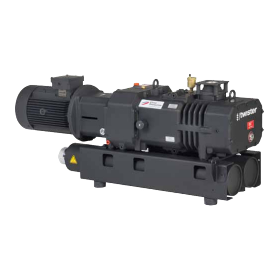
Set up and operation Set up and operation Setup S-VSI 300 (44) Fig. 2 Vacuum pump S-VSI 300 (44) Vacuum port Motor data plate H, H Oil fill ports hot surfaces > 158°F I, I Oil sight glass Thermostat (optional) K, K Oil drain plugs Liquid level switch (optional) - Page 13 Set up and operation S-VSI 300 (44) Fig. 3 Vacuum pump S-VSI 300 (44) Vacuum port Oil recommendation plate Exhaust air outlet Data plate Cooling water inlet G ½" Vent valve Cooling water outlet G ½" Discharge silencer Cooling water drain Cooling air intake Cooling air outlet www.elmorietschle.com ©...
-
Page 14: Data Plate
Set up and operation 4.1.1 Data plate Model designation Serial number Year of construction SN: SC10128914001 / 2013 Item no. vacuum pump Suction capacity S-VSI 300 (42) ID:10270442BL 0,1 mbar (abs.) 320 m³/h Ultimate vacuum (abs.) RPM speed EN 60034 5,50 kW 2880/min S1 100%... -
Page 15: Areas Of Application
Set up and operation Areas of application The VSI pumps are suitable for the evacuation of closed volumes for a continuous vacuum within a pressure range of: 0.075 to 760 Torr. They are also suitable for handling humid gas streams due to its high water vapor tolerance. The maximum pumping capacity is 224 cfm at 60 Hz. -
Page 16: Cooling The Pump
Set up and operation Cooling the pump 4.4.1 Continuous flow cooling (Optional) Cooling water flows continuously through the cavity in the double walled compressor housing. For safety reasons the cooling system is fitted with a solenoid valve, temperature control and a safety valve (optional). -
Page 17: Installation
Installation Installation Preparing for installation Check the following points: • Pump is freely accessible from all sides • Do not block ventilation grids and holes • Sufficient room for installing and removing pipes and for maintenance work, particularly for installing and dismantling the pump • No external vibration effects • Do not draw in any hot exhaust air from other pumps into the cooling system. The oil fill ports (Fig. 2/H, H ), oil sight glass (Fig. -
Page 18: Connecting Pipes
Installation Connecting pipes a) Vacuum connection at (Fig. 2/A, 3/A). NOTICE Damage to the threaded inlet connection may result from excessive torque during the installation of the process piping. Use only the sufficient amount of torque to obtain a sealed connection. -
Page 19: Connecting The Cooling Water Pipe
Installation Connecting the cooling water pipe NOTICE Cooling water! The vacuum pump must not be operated without cooling water. Potential pump failure Ensure that the cooling water flow is not interrupted. a) Connect the cooling water pipe to the cooling water inlet (Fig. 3/C) and the cooling water discharge pipe to the cooling water outlet (Fig. -
Page 20: Filling With Lubricating Oil
Installation b) When connecting a circulating cooling system to an external cooling system, it must be filled with cooling fluid. NOTICE Rinse the pipe network on the process side before connecting it A filter element must be installed in the pipe network to prevent foreign debris getting into the heat exchanger. -
Page 21: Connecting The Motor
Installation Connecting the motor DANGER Improper electrical connections may cause severe injury or death! The electrical installation may only be done by a qualified, licensed electrician observing local codes and regulations. The customer must provide a main disconnect switch. a) The motor’s electrical data is given on the data plate (Fig. -
Page 22: Commissioning And Decommissioning
Commissioning and decommissioning Commissioning and decommissioning Commissioning WARNING Improper use May lead to severe or fatal injuries. Therefore be sure to obey the safety instructions. CAUTION Hot surfaces When the pump is at operating temperature the surface temperatures on the components (Fig. -
Page 23: Checking The Rotation Direction
Commissioning and decommissioning 6.1.1 Checking the rotation direction The drive shaft direction of rotation is shown by the rotation direction arrow (Fig. 2/O) on the motor flange. a) Start the motor briefly (max. two seconds) to check the direction of rotation. When looking at the motor fan, it must rotate clockwise. -
Page 24: Decommissioning/ Storing
Commissioning and decommissioning Decommissioning/ storing Stop the pump a) Switch the pump off. b) Close isolation valve to pump inlet. c) Disconnect the motor from the power supply. d) Open isolation valve slowly to vent the pump to atmosphere. e) Remove the pipes and hoses. Seal the connections for suction and discharge ports with adhesive foil. -
Page 25: Maintenance And Repair
Maintenance and repair Maintenance and repair DANGER Electrical Warning! Before performing any maintenance, disconnect power to motor at main power switch or circuit breaker. Install a lock-out tag to ensure power remains off during the service procedure. WARNING Hot surfaces and equipment During maintenance work there is the danger of getting burned from hot components (Fig. -
Page 26: Changing The Oil
Maintenance and repair 7.2.1 Changing the oil Fig. 9 Changing the oil NOTICE H, H Oil fill ports Always change the oil when the pump is at I, I Oil sight glass operating temperature and in a ventilated area. If the oil sump is not completely emptied the K, K Oil drain plugs amount that can be refilled is reduced. - Page 27 Maintenance and repair 7.2.2 Inlet Filtration Fig. 10 Inlet Filtration NOTICE Suction flange Insufficient maintenance of the air filter Mesh filter The capacity of the pump is reduced and damage may occur to the pump. Screws Gas ballast valve Intake air filter: The mesh filter (Fig.
- Page 28 Maintenance and repair Gas ballast valve filter: The pump has a gas ballast valve (Fig. 10/U). The filter disc (Fig. 11/f ) must be replaced every 7,500 hours. The micro filter screens (Fig. 11/f must be cleaned at the same time. By undoing the countersunk screw (Fig.
-
Page 29: Coupling
Maintenance and repair 7.2.3 Drive Coupling The coupling insert (Fig. 13/k) is subject to wear and must be checked regularly (at least once a year). CAUTION Damaged or worn coupling insert may lead to rotor shaft breakage. To inspect the coupling, switch off the motor and lock out the power supply. -
Page 30: Repair/ Service
Maintenance and repair Repair/ Service a) For on-site repair work the motor must be disconnected from the power supply by a qualified electrician. Please contact the Elmo Rietschle for the a of the service center in your area. b) After any repairs, please follow all guidance listed under “Installation”... -
Page 31: Spare Parts
Maintenance and repair Spare parts Order spare parts in accordance with the: • Spare parts list: E 832/4 ➝ S-VSI 300 (44) • Download the pdf file: http://www.elmorietschle.com ➝ Downloads ➝ Product Documents ➝ S-Series ➝ Spare Parts • Parts subject to wear and gaskets are indicated separately on the list. • Web site: http://www.service-er.de • Select the type, size and design. -
Page 32: Malfunctions: Causes And Elimination
Malfunctions: Causes and elimination Malfunctions: Causes and elimination Fault Cause Troubleshooting Important Pump is switched Power Supply/ Frequency Check by qualified electrician Section 5.5 off by the motor does not correspond with the protection switch motor data Connection to motor leads is not correct Motor protection switch is not set correctly... - Page 33 Deposits on the rotors Clean the compression Elmo Rietschle abnormal noise chamber and the rotors Service Please contact Elmo Rietschle Service for other malfunctions or those that cannot be eliminated. www.elmorietschle.com © Gardner Denver Schopfheim GmbH, Gardner Denver Deutschland GmbH...
-
Page 34: Technical Data
Technical Data Technical Data 300 (44) S-VSI 10 Hp Sound pressure level (max.) 50 Hz 150 ➝ 0.075 Torr dB(A) EN ISO 3744 60 Hz Tolerance ± 3 dB(A) Weight * Length * 52.23 Width 17.87 Height 22.83 Vacuum connection 2" NPT Correct amount of oil (1.2 ➝... - Page 36 www.elmorietschle.com ElmoRietschle@gardnerdenver.com Gardner Denver, Inc. 1800 Gardner Expressway Quincy, IL 62305 Telephone: 866-249-2275...
Need help?
Do you have a question about the S-VSI 300 (44) and is the answer not in the manual?
Questions and answers