Table of Contents
Advertisement
Quick Links
Advertisement
Table of Contents

Subscribe to Our Youtube Channel
Related Manuals for Haag-Streit VISUTRON 900 Touch


Summary of Contents for Haag-Streit VISUTRON 900 Touch
- Page 1 VISUTRON 900 Touch User’s Guide...
- Page 2 ©2019 AMETEK, Inc. Reichert, Reichert Technologies, Phoroptor, and ClearChart are registered trademarks of Reichert, Inc. LensChek and OptoChek are trademarks of Reichert, Inc. Bluetooth is a registered trademark of Bluetooth SIG. AMETEK is a registered trademark of AMETEK, Inc. All other trademarks are property of their respective owners. The information contained in this document was accurate at time of publication.
-
Page 3: Table Of Contents
Unpacking Instructions ............................ 9 Parts Identification ............................9 Connecting the Visutron 900 Touch System ....................11 Connecting a Right or Left Mount Visutron 900 Touch ................. 12 Connecting with Cables ..........................13 Connecting with Bluetooth Dongles ......................14 Bluetooth Dongle LED Lights Description ..................... 16 Connecting with Bluetooth USB (ClearChart 4 Series Only) ................ - Page 4 Service Menu ..............................72 Specifications ..............................75 Classifications ............................... 76 Guidance Tables ..............................77 Appendix A - Compatibility Chart ......................... 81 Appendix B - Visutron 900 Touch, Lensmeter, and Auto Refractor Data ............. 82 Warranty ................................83 16243-101 Rev. G...
-
Page 5: Symbol Information
Symbol Information Symbol Information The following symbols appear on the instrument. Refer to Instruction Manual Caution Type B Product Classification Protective Earth Alternating Current Power ON / OFF Date of Manufacture 2019 Catalog Number Serial Number Waste of Electrical and Electronic Equipment Compliance to Medical Device Directive 93/42/EEC Authorized to mark given by Intertek ETL Semko for conformance with electrical standards... -
Page 6: Warnings And Cautions
Warnings and Cautions Warnings and Cautions Reichert Technologies (Reichert ) is not responsible for the safety and reliability of this instrument when ® ® unauthorized dealers or persons assemble, disassemble, repair, or modify the instrument, or when a person does not use the instrument in accordance with this User’s Guide. WARNING: AN INSTRUCTION THAT DRAWS ATTENTION TO THE RISK OF INJURY OR DEATH. - Page 7 Warnings and Cautions (continued) Warnings and Cautions (continued) WARNING: PRIOR TO INSTALLING THE PHOROPTOR HEAD ONTO THE STAND ARM, VERIFY THAT THE ROD ON THE STAND ARM IS SECURE BEFORE ATTEMPTING TO INSTALL THE PHOROPTOR HEAD OR YOU MIGHT DAMAGE THE UNIT AND/OR INJURE THE PATIENT. WARNING: OTHER ELECTRICAL OR ELECTRONIC EQUIPMENT CAN INTERFERE WITH THE BLUETOOTH WIRELESS CONNECTION TRANSMITTERS OR RECEIVERS, EVEN IF THAT EQUIPMENT ALSO COMPLIES WITH CISPR EMISSIONS REQUIREMENTS.
-
Page 8: Introduction
Please retain this guide for future reference and to share with other users. For additional copies of this manual or questions related to the Visutron 900 Touch, contact your local authorized Reichert dealer, or contact our Customer Service department directly:... -
Page 9: Instrument Setup
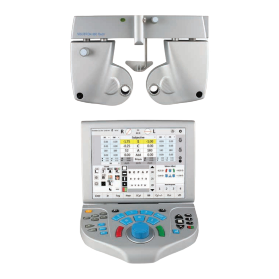
Please retain the original packaging and use it if future transportation of the instrument is required. The main components of the Visutron 900 Touch are packed in two separate boxes. The first box contains the Phoroptor Head and Reading Rod, the second box contains the Central Unit, Controller, and Accessories Box. - Page 10 Instrument Setup (continued) Parts Identification (continued) Controller Central Unit Phoroptor Head 16 15 Figure IS-01, Parts Identification 1. Illuminated Bubble Level & Power Indicator Light 13. EMR Connection Port for connecting to a computer 2. Threaded Screw for Near Vision Rod 14.
-
Page 11: Connecting The Visutron 900 Touch System
WARNING: POSITION THIS INSTRUMENT SO THE PLUG IS EASILY ACCESSIBLE. WARNING: DO NOT PLUG IN THE CENTRAL UNIT UNTIL THE VISUTRON 900 TOUCH SYSTEM IS FULLY SETUP. The basic system setup contains three components programmed to interact with each other: the Phoroptor Head, the Central Unit, and the Controller. -
Page 12: Connecting A Right Or Left Mount Visutron 900 Touch
Refer to the Connecting with Internal Bluetooth section if connecting with Bluetooth. Connecting a Right or Left Mount Visutron 900 Touch Figure IS-05A, Connection Diagram Connect the Visutron 900 Touch using the connection cable (559-276) according to Figure IS-05A. 16243-101 Rev. G... -
Page 13: Connecting With Cables
Instrument Setup (continued) Connecting with Cables The Visutron 900 Touch can connect to multiple Pro- jectors, Lensmeters, and Autorefractors easily with a wired connection. Refer to the instructions below to connect instruments with a cable. 1. Tap Settings, located at the top right of the Figure IS-06, Settings Controller screen. -
Page 14: Connecting With Bluetooth Dongles
(continued) Connecting With Bluetooth Dongles Reichert developed a Bluetooth dongle to connect external devices wirelessly to the Visutron 900 Touch. To communicate properly, the Bluetooth dongle must be paired with a specific port on the Central Unit. Perform the following steps in order to configure each Bluetooth dongle. - Page 15 Central Unit port with the provided pairing cable. Refer to Figure IS-13. 10. In the Port Settings panel on the Visutron 900 Touch controller tap Pair. Refer to Figure IS-14. CAUTION: DO NOT TAP PAIR AGAIN. IF PAIR IS ACTIVATED, IT WILL BE NECESSARY TO REPEAT THE ABOVE PROCE- DURE TO RE-ESTABLISH THE WIRELESS CONNECTION.
-
Page 16: Bluetooth Dongle Led Lights Description
Instrument Setup (continued) Connecting With Bluetooth Dongles (continued) Note: The LED will blink red if the connection fails. Note: If the Bluetooth dongle was successfully paired, “Connected” will appear in the upper right corner of the panel. Refer to Figure IS-18. If “Failed” appears, then press and hold the Bluetooth dongle’s reset switch, using an appropriate object (e.g., paperclip) for approximately 2 seconds. -
Page 17: Connecting With Bluetooth Usb (Clearchart 4 Series Only)
9. Press the Menu button on the ClearChart remote and view the Bluetooth address in the lower right corner of the ClearChart. Refer to Figure IS-20. 10. Tap Discover on the Ports page and the Visutron 900 Touch will search for all available ClearChart Digital Acuity Systems. Refer to Figure IS-19. - Page 18 Instrument Setup (continued) Connecting With Bluetooth USB (ClearChart 4 Series Only) (continued) Note: If the desired Bluetooth USB device is not found, tap the Discover button again. 11. Once the Bluetooth address is displayed, select the address that matches the address on the ClearChart and tap Pair.
-
Page 19: Emr Setup
EMR Setup The Visutron 900 Touch can connect to an EMR system one of two ways, depending on the capability of the EMR system. Contact the EMR company to find out if the specific EMR system is configured to sup- port one-way or two-way communication. -
Page 20: Setup
4. In the Port Settings panel, select the device according to the list below. Devices Visutron 900 Touch - Sends Visutron 900 Touch final refraction data only (including subjective re- fraction data and binocular test results). Visutron 900 Touch Exp - Sends Visutron 900 Touch final refraction data (including subjective re- fraction data and binocular test results) and pre-test data. -
Page 21: Printer
Instrument Setup (continued) Printer 1. Tap Settings, located at the top right of the Controller screen. 2. Tap Ports on the Settings menu. 3. In the Port Selection panel, tap Printer. Refer to Figure IS-27. 4. In the Port Settings panel, select the MCP1000. Refer to Figure IS-27. 5. -
Page 22: Daisy Chaining Multiple Visutron 900 Touch Systems
Touch units, Daisy chaining is required to get the pre-test data to all of the Visutron 900 Touch units. Pre- test equipment is sent to the first Visutron 900 Touch in the chain, and the data is then sent to all of the other Visutron 900 Touch systems via the Instrument 1 or 2 and Transfer ports as shown in Figure IS-28. -
Page 23: Connecting With Internal Bluetooth
Figure IS-29, Bluetooth Address 7. Repeat all the above steps for the Instrument 1 port on the Visutron 900 Touch that is having the data transferred to it. Be sure that under Device, AutoPhor Receive is selected. Refer to Figure IS-31. -
Page 24: Near Vision Rod And Card
Instrument Setup (continued) Near Vision Rod and Card The Visutron 900 Touch includes a Near vision rod, and a near vision card attached to a card illuminator. Place the three AAA batteries in the card illuminator. Slide the card illuminator onto the near vision rod. Loosen the convergence lever thumb screw, install the rod into the convergence lever, and tighten the thumb screw. -
Page 25: Controller Keypad
Instrument Setup (continued) Controller Keypad 10 11 26 25 23 22 Figure IS-33, Controller Keypad 1. C—Clear 17. Enter Key 2. AR—Auto Refractor 18. Green button for Split Prism Test 3. LM—Lensmeter 19. L—Open Left Eye, Close Right Eye 4. R—Right Eye Occluder 20. -
Page 26: Lens Buttons
Press the different types of but- tons (S, C, A, Add) to activate different sets of lenses in the Visutron 900 Touch Head. Enters Clear Mode, to enable the clearing of individual data or all of the data. Occludes the right eye. -
Page 27: Chart Buttons
Single Optotype Displays one single optotype. Red/Green Displays red/green filter on selected optotype. Each half contains identical optotypes. In & Out Buttons These buttons access incoming pre-test data or export outgoing exam data. Presents pre-test equipment data imported into the Visutron 900 Touch. OUT Sends data out to the EMR system or prints the data. The specific data sent is selected in the Settings menu. 16243-101 Rev. G... -
Page 28: Quick Comparison Buttons
SUBJ This button presents the current subjective data in the Visutron 900 Touch head. This button presents the autorefractor data in the Visutron 900 Touch head. This button presents the plano lenses in the Visutron 900 Touch head. SC stands for ‘sine- correctore’, or ‘without’ correction. -
Page 29: Controller Screen
Instrument Setup (continued) Controller Screen Figure IS-34, Display Screen 1. Date and Time 13. Acuity Chart Masks 2. Exam Time 14. On/Off for Darkening Acuity Chart Display 3. Right and Left Apertures 15. Menu Bar 4. Pupillary Distance 16. Near Vision Toggle 17. -
Page 30: Top Menu Bar
2. Lensmeter Data -entered electronically or manually. 3. Active Data Field - the lenses currently in the Visutron 900 Touch. This can be swapped out with any of the other data sets at any time. The individual measure- ment boxes are one of three colors: White - Active field that can be adjusted. -
Page 31: Acuity Chart Menu
Instrument Setup (continued) Controller Screen (continued) Acuity Chart Menu 1. Charts - Easy access to the favorite charts that were selected in the Settings menu. Tapping a chart will display that chart on the acuity system. 2. Chart Masks - Multiple lines, single horizontal line, single vertical line, single optotype, and red/green masks are avail- able. -
Page 32: Program
Instrument Setup (continued) Controller Screen (continued) Program This section displays the available programs. When a program is selected, this will change to display the current, previous, and follow- ing step in the program, as well as controls to pause or stop the program. Bottom Menu Bar 1. -
Page 33: Auxiliary Lenses Or Filters
Instrument Setup (continued) Controller Screen (continued) Auxiliary Lenses or Filters Tap the Auxiliary Lenses icon to access the auxiliary lenses and filters. The bottom Selection Bar will change to display the available Auxiliary Lenses and Filters. Tap the icon again to exit the menu. -
Page 34: Settings
Instrument Setup (continued) Settings The Settings menu is accessible from the Main screen, by tapping the gear icon on the top right corner. 1. Tap Settings, located at the top right of the Controller screen. 2. To modify a setting, tap the box of the setting to reveal a drop-down list of options. 3. - Page 35 Instrument Setup (continued) Settings (continued) Settings Options (continued) Prism Units Retinoscopy • X/Y coordinates • Sphere +1.5 D (Base In, Base Out, Base Up, Base • Sphere +2.0 D Down) • Polar (Polar coordinates) Fog Amount BB Fog Amount Select the amount of auto-fogging preferred: Select the amount of auto-fogging preferred for •...
- Page 36 Instrument Setup (continued) Settings (continued) Settings Options (continued) XCyl Auto XCyl Mode If Xcyl Auto is on, the XCyl Mode selected Specifies the type of XCyl test that automatically below automatically begins when Cylinder starts when a XCyl test is selected. or Axis is selected on the Main Screen or •...
- Page 37 The subjective refraction data sent to EMR and the printer is adjusted according to the selected vertex distance. The CVD of the Visutron 900 Touch head is 16mm and the values displayed in the main data area are shown using that CVD. The subjective refraction data sent to EMR and the printer is adjusted according to the vertex distance selected here.
-
Page 38: Programs
Instrument Setup (continued) Programs Custom refraction steps can be recorded in up to four different programs. Programs are run by tapping the number of the program at the bottom right of the main screen. Creating a Program 1. Tap Programs in the bottom bar of the Settings menu. 2. -
Page 39: Modifying And Deleting Steps
Note: The copied program replaces any previously existing steps in the selected program. Exporting a Program Programs can be exported onto a thumb drive and then imported into another Visutron 900 Touch. This is a fast way to have the same programs put on multiple Visutron 900 Touch units. -
Page 40: Charts
Instrument Setup (continued) Charts The top half of the Charts screen contains all available charts. The lower left section contains the preferred charts. These charts are visible on the main screen and are quickly accessible when performing a refrac- tion. The lower right section displays the chosen charts assigned to specific tests. Refer to Figure IS-37. Selecting a Preferred Chart 5. -
Page 41: Performing An Exam
Figure PE-01, Thumb Screw point for the refraction, and PD was not manually adjusted, the Visutron 900 Touch Head automatically moves to adjust to that PD. 6. Press the PD button, or tap PD at the top of the screen. Both apertures display the crosshair lenses. -
Page 42: Data Input
Direct Connection - The lensmeter and autorefractor are directly connected to the Visutron 900 Touch using a serial cable or Bluetooth adapter, and their data populates the AR and LM data fields. • Imported Data List - The pre-test data is sent directly to the Visutron 900 Touch and the data are stored in a Data List. •... -
Page 43: Direct Connection
Performing an Exam (continued) Data Input (continued) Inputting Data Electronically (continued) Direct Connection The measurement data from the Lensmeter and Auto Refractor directly populates the LM and AR data fields in the Controller display. The data transfer takes place when the user presses the data output but- tons on each pre-test device. -
Page 44: Entering Data Manually
Performing an Exam (continued) Data Input (continued) Entering Data Manually Unlock Icon 1. Tap the drop-down list in the main display area to open a list of different data sets. Refer to Figure PE-06. 2. Select the type of data to enter. To enter auto refractor data, tap the AR option in the drop-down list or press the AR button. -
Page 45: Starting A Refraction From Previously Saved, Transferred, Or Input Data
Performing an Exam (continued) Starting a Refraction From Previously Saved, Transferred, or Input Data 1. Tap the drop-down list in the center display area or press the AR or LM button on the keypad to select the data to be used (e.g., LM, AR). The data from the boxes are transferred to the active refraction data field. -
Page 46: The Basics
Performing an Exam (continued) The Basics Eye Selection Press the R, L, or B button to open the apertures for the right eye, left eye, or both eyes, respectively . The aperture for the inactive eye automatically closes during refraction. The default setting for the open aperture at the start of a new exam is selected in the Setup Menu. -
Page 47: Adjusting Sphere
Performing an Exam (continued) The Basics (continued) Adjusting Sphere 1. Activate the Sphere value field. 2. Turn the CONTROL KNOB to adjust the Sphere value by ±0.25 D, or press and turn the CONTROL KNOB to adjust the Sphere value by ±1.00 D per click stop. -
Page 48: Cross Cylinder
Performing an Exam (continued) Cross Cylinder 1. Tap XCyl in the menu bar at the bottom of the main screen, or Press both the C and A buttons to activate the Cross Cylinder function. 2. If the XCyl Mode setting is set to “User Select,” three test options display: Manual, Smart, or Split Cyl. •... -
Page 49: Manual Test
Performing an Exam (continued) Cross Cylinder (continued) Manual Test Note: Tap Test to switch the type of XCyl test (Manual/Smart/Split Cyl). The Manual Cross Cylinder test allows the user to refine Axis in 1°, 5°, or 10° increments, and adjust Cylinder in ±0.25 D, ±0.50 D, or ±1.00 D increments. - Page 50 Performing an Exam (continued) Cross Cylinder (continued) Manual Test (continued) 8. Turn the CONTROL KNOB to present position 1 and position 2 to the patient. In the lens aperture at the top of the screen, the blue line indicates the axis of increased cylinder value presented to the patient.
-
Page 51: Smart Test
Performing an Exam (continued) Cross Cylinder (continued) Smart Test Note: Tap Test to switch the type of XCyl test (Manual/Smart/Split Cyl). 1. Tap XCyl on the menu bar at the bottom of the main screen. 2. Tap Smart to begin the Smart Cylinder test. Spherical equivalent is maintained during Cylinder power adjustment. - Page 52 Performing an Exam (continued) Cross Cylinder (continued) Smart Test (continued) 8. Turn the CONTROL KNOB to present position 1 and position 2 to the patient. The amount of Cyl change is indicated in the lens aperture at the top of the screen. 9.
-
Page 53: Split Cyl Test
Performing an Exam (continued) Cross Cylinder (continued) Split Cyl Test Note: Tap Test to switch the type of XCyl test (Manual/Smart/Split Cyl). The Split Cyl Cross Cylinder test shows the patient two charts at the same time when adjusting Axis and Cylinder. -
Page 54: Binocular Balance
Performing an Exam (continued) Binocular Balance 1. Press the BB button, or tap BB on the main screen, to begin Binocular Balance. 2. The Binocular Balance test automatically places prism in each eye (3D base down in the right eye and 3D base up in the left eye), and fogs the left and right eye. -
Page 55: Near Vision Test
Performing an Exam (continued) Near Vision Test 1. Lower the Near Vision rod. • The Add boxes are highlighted. • Both apertures are open. • Phoroptor head converges to 15.75 in. (40 cm). Note: The NearBright automatically illuminates when the Near Vision rod is lowered. 2. -
Page 56: Fused Cross Cylinder Test
Performing an Exam (continued) Near Vision Test (continued) Fused Cross Cylinder Test 1. Select the Cross Grid Chart on the reading card. Note: The Fixed Cross Cylinder lenses (+0.50 D, Axis 90°) are placed in the lens apertures. 2. Ask the patient: “Which is better (sharper and clearer), the horizontal or the vertical lines?” 3. -
Page 57: Amplitude Of Accommodation Test
Performing an Exam (continued) Near Vision Test (continued) Amplitude of Accommodation Test 1. Tap the Accommodation screen icon to measure the Amplitude of Accommodation or Accommoda- tive Response. Note: Amplitude of Accommodation is measured monocularly. 2. Turn the CONTROL KNOB to add minus (-) power to the right eye (using the patient’s Near Vision addition as the starting point), until the patient states that the target blurs. -
Page 58: Prism Testing
(continued) Prism Testing Prism lenses move in automatically when the prism test is engaged. Not all models of the Visutron 900 Touch come with prism compensa- tors. 1. Press the PRISM button, or tap Prism, to begin the Prism test. -
Page 59: Phoria
Performing an Exam (continued) Prism Testing (continued) Phoria Phoria Testing - Distance 1. Press the PRISM button, or tap Prism. 2. Tap Phoria in the menu bar at the bottom of the screen. Note: The Phoria test automatically places Prism power of 6 D BD in the right eye and 10 D BI in the left eye. -
Page 60: Vertical Phorias Test
Performing an Exam (continued) Prism Testing (continued) Phoria (continued) Complete the Phoria Test Tap Set Prism to set the patient’s Prism values to that determined by the Phoria test or tap Save to exit the test and return the prisms to their previous values. Phoria Testing - Near 1. -
Page 61: Vergence
Performing an Exam (continued) Prism Testing (continued) Vergence Vergence Testing or Fusion Range Measurement - Distance 1. Press the PRISM button, or tap Prism. 2. Tap Vergence in the menu bar at the bottom of the screen. This test automatically advances through the steps of measuring: •... -
Page 62: Infraergence
Performing an Exam (continued) Prism Testing (continued) Vergence (continued) Infravergence and Supravergence can now be measured in each eye. Infravergence 1. Enter BD prism slowly, until the patient sees two images. 2. Press the CONTROL KNOB, or tap Break. 3. Enter BU prism until the images converge again. 4. -
Page 63: Vertex Distance Calculator
Tap SE to display the spherical equivalent. Close the Vertex Distance Calculator by tapping Exit. Note: The Vertex Distance Calculator is for reference only. The Visutron 900 Touch does not send the adjusted data out. -
Page 64: Comparing Refraction Data
Performing an Exam (continued) Comparing Refraction Data One of the advantages of the Visutron 900 Touch is the abil- ity to quickly and easily compare different refractions with the push of a button, enabling patients to see the difference between old and new prescriptions, or the difference between two possible prescriptions. -
Page 65: Emr And Printing
It is essential to either send the refraction data to an EMR system or the printer before clearing data and preparing for the next patient. The refraction data is not stored in the Visutron 900 Touch, so it cannot be recalled for reference at a later time. -
Page 66: Data Output
Performing an Exam (continued) EMR and Printing (continued) Data Output Each patient data record includes: • Sphere (Right and Left Eye, Far and Near) • Cylinder (Right and Left Eye) • Axis (Right and Left Eye) • Prism (Right and Left Eye) •... -
Page 67: Clear
Clearing All Data Press the C button, or tap Clear, to clear all the data. This will reset the entire exam and prepare the Visutron 900 Touch for the next patient. Reset Head Tap Reset Head to reinitialize the Phoroptor head. -
Page 68: Cleaning And Maintenance
Head to Reichert if interior lens cleaning is necessary. To ensure that the Visutron 900 Touch Head remains clean, cover the Phoroptor Head with the dust cover when not in use. Consistent use of the dust cover will help keep dust and other contaminants off of the unit and from getting inside and possibly affecting operation. - Page 69 Cleaning and Maintenance (continued) Cleaning (continued) Forehead Rest Cleaning and Disinfection For hygienic reasons, the Forehead Rest may be cleaned with a clean cloth moistened with a mild deter- gent solution (1 cc of liquid dish soap to one liter of clean, filtered water (filtered below 5 microns)). Note: If the Forehead Rest must be sanitized, a 70% isopropyl alcohol wipe may be used.
-
Page 70: Troubleshooting
Troubleshooting Troubleshooting Only those errors indicated on the display are directly important to the user and are listed below. In case of support requests, please refer to the Error Log File (Settings - Service - Show Error Log File) where a detailed listing of all errors, warnings, and status messages are located. - Page 71 Troubleshooting (continued) Troubleshooting (continued) Error Source Probable Cause Solution No image in the display • Failure of fuses on the cable plug of • Exchange the fuses on the cable plug despite switched-on unit. the central unit. of the central unit. •...
-
Page 72: Service Menu
Transfer Driver - The device driver activated for the Transfer port. The Service Menu screen allows the user to set the date and time on the Visutron 900 Touch. Please have the system information on this page ready when contacting Reichert Technical Services. - Page 73 Troubleshooting (continued) Service Menu (continued) Set Date/Time 1. Tap + or - in the Set Date/Time box to change the date and time. 2. Tap Set to set the date and time. Import Settings and Export Settings Import Settings Import Settings allows the user to import settings from a USB drive. Export Settings Export Settings allows the user to export the current settings to a USB drive.
- Page 74 The following list explains the sounds: • Beep - Indicates an error message or that certain keys are not active when performing certain operations in the Visutron 900 Touch. • Chirp - Indicates that a test or function completed successfully.
-
Page 75: Specifications
Specifications Specifications REF 16241 / 16242 Physical Dimensions Phoroptor Head Spherical Effects ....................+17.75 to -22.25 D Steps ........................... 0.25 and 1.0 D Cylinder Power ......................-8.0 to +8.0 D Steps ........................... 0.25 and 1.0 D Axis Adjustment ........................0° to 180° Steps .......................... -
Page 76: Classifications
50 kPa 106 kPa (31.3 in. Hg) Disposal Dispose of the Visutron 900 Touch in accordance with local regulations. The Visutron 900 Touch con- tains no hazardous materials. Software Revision The software version is located in the Service Menu in the Controller, or by contacting Reichert with the Central Unit serial number. -
Page 77: Guidance Tables
All Medical Electrical Equipment and Medical Electrical Systems Guidance and Manufacturer’s Declaration – Electromagnetic Emissions The Visutron 900 Touch is intended for use in the electromagnetic environment specified below. The customer or user of the Visutron 900 Touch should ensure that it is used in such an environment. Electromagnetic Environment Emissions Test... - Page 78 All Medical Electrical Equipment and Medical Electrical Systems Guidance and Manufacturer’s Declaration – Electromagnetic Immunity The Visutron 900 Touch is suitable for use in electromagnetic environment specified below. The customer or user of the Visutron 900 Touch should ensure that it is used in such an environment. Immunity IEC 60601...
- Page 79 Medical Electrical Equipment and Medical Electrical Systems that are NOT Life-supporting Guidance and Manufacturer’s Declaration – Electromagnetic Immunity The Visutron 900 Touch is intended for use in the electromagnetic environment specified below. The customer or user of the Visutron 900 Touch should ensure that it is used in such an environment. Immunity IEC 60601...
- Page 80 The Visutron 900 Touch is intended for use in the electromagnetic environment in which radiated RF disturbances are controlled. The customer or user of the Visutron 900 Touch can help prevent electromagnetic interference by maintaining a minimum distance between portable and mobile RF Communications Equipment and the Visutron 900 Touch as recommended below, according to the maximum output power of the communications equipment.
- Page 81 Guidance Tables (continued) Table 9 – Guidance and Manufacturer’s Declaration Electromagnetic Immunity Immunity to Proximity Fields from RF Wireless Communications Equipment Guidance and Manufacturer’s Declaration - Electronic Immunity The Visutron 900 Touch is intended for use in the electromagnetic environment as specified below related to proximity fields from RF wireless communications equipment. Electromagnetic Immunity Compliance IEC 60601Test Level Environment...
-
Page 82: Appendix A - Compatibility Chart
Appendices Appendix A - Compatibility Chart WARNING: ANY NON-MEDICAL ELECTRICAL EQUIPMENT USED WITH THE VISUTRON 900 TOUCH MUST BE COMPLIANT WITH APPLICABLE IEC OR ISO SAFETY STANDARDS. Auto Refractors Lensmeters REICHERT RK600/700 REICHERT AL 200 REICHERT OPTOCHEK REICHERT AL 500 ™... -
Page 83: Appendix B - Visutron 900 Touch, Lensmeter, And Auto Refractor Data
Data output from the printer will now always include final subjective refraction data from the Visutron 900 Touch and Auto Refractor and Lensmeter data if they were sent to the Visutron 900 Touch. This is a sample of the printer data output. -
Page 84: Warranty
Warranty Warranty and Limitation of Liability This product is warranted by Reichert Technologies (“Reichert”) against defective material and workmanship under normal use for a period of two years from the date of invoice to the original purchaser. (An authorized dealer shall not be considered an original purchaser.) Under this warranty, Reichert’s sole obligation is to repair or replace the defective part or product at Reichert’s discretion. - Page 85 Notes 16243-101 Rev. G...
- Page 86 Notes 16243-101 Rev. G...
- Page 87 Notes 16243-101 Rev. G...
- Page 88 Reichert, Inc. 3362 Walden Ave Suite 100 Depew, NY 14043 Toll Free: 888-849-8955 Phone: 716-686-4500 Fax: 716-686-4555 Email: reichert.information@ametek.com www.reichert.com AMETEK GmbH Business Unit Reichert Carl-von-Linde-Strasse 42 85716 Unterschleissheim/Munich Germany Email: info.reichert-de@ametek.com Tel: +49 (89) 315 8911 0 Fax: +49 (89) 315 891 99 ISO 13485 Certified 16243-101 Rev.
Need help?
Do you have a question about the VISUTRON 900 Touch and is the answer not in the manual?
Questions and answers