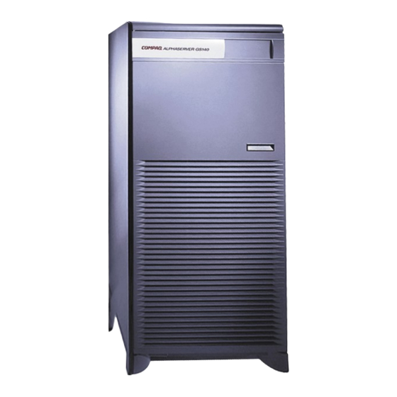
Compaq AlphaServer GS140 Getting Started
With logical partitions
Hide thumbs
Also See for AlphaServer GS140:
- Quick specification (25 pages) ,
- Operation manual (346 pages)
Table of Contents
Advertisement
Quick Links
Download this manual
See also:
Operating Manual
AlphaServer GS140
Getting Started with Logical Partitions
Order Number: EK–TUNLP–SF
This document describes the hardware configuration rules and
the console firmware commands and environment variable
settings needed to run multiple instances of an operating system
on Compaq AlphaServer GS140 systems.
Advertisement
Table of Contents

Related Manuals for Compaq AlphaServer GS140


Summary of Contents for Compaq AlphaServer GS140
- Page 1 AlphaServer GS140 Getting Started with Logical Partitions Order Number: EK–TUNLP–SF This document describes the hardware configuration rules and the console firmware commands and environment variable settings needed to run multiple instances of an operating system on Compaq AlphaServer GS140 systems.
- Page 2 The software may be used or copied only in accordance with the terms of the agreement. COMPAQ and the Compaq logo are registered in United States Patent and Trademark Office. Tru64 is a trademark of Compaq Computer Corporation. AlphaServer and OpenVMS are trademarks of Digital Equipment Corporation.
-
Page 3: Table Of Contents
Contents Preface Chapter 1 Introduction Reasons for Partitioning Important Considerations for Partitioned Systems Overview of the Partitioning Process Chapter 2 Configuration Rules Overview of Configuration Requirements Example of a Partitioned System Module Configuration Memory Allocation 2.4.1 Two Partitions 2.4.2 Three Partitions 2-10 DWLPB PCI Card Cages and Hose Connections 2-12... - Page 4 Step 3: Set and Initialize Environment Variables, Boot/Install from Secondary Consoles 4-10 Chapter 5 Tips and Troubleshooting Setting auto_action Within Partitions How to Stop a Hung Secondary Partition Halting All Partitions to Reconfigure Correcting Errors in Environment Variables Using Tools to Debug a Partition 5-10 Index Examples...
- Page 5 Construction of Three-Partition I/O Bit Masks Construction of Two-Partition I/O Bit Masks Setting auto_action to Halt in Each Partition Debugging One Partition 5-10 Tables Related AlphaServer GS140 Documentation viii Requirements for a Three-Partition System Requirements for a Two-Partition System Environment Variables for Logical Partitions...
-
Page 7: Preface
Preface Intended Audience This manual is written for anyone wishing to understand the concepts and requirements of logical partitions for a Compaq AlphaServer GS140 system, as well as how to use the console firmware to define them. Document Structure This manual uses a structured documentation design. Topics are organized into small sections for efficient online and printed reference. -
Page 8: Related Alphaserver Gs140 Documentation
Documentation Titles Table 1 lists the books in the AlphaServer GS140 documentation set and operating system documentation that you may find useful. Table 1 Related AlphaServer GS140 Documentation Title Order Number Hardware User Information and Installation Operations Manual EK–T8030–OP QZ–00RAC–GC... -
Page 9: Chapter 1 Introduction
Each instance is maintained at a separate console monitor, as shown for two partitions in Figure 1–1. The AlphaServer GS140 system supports up to three partitions. Figure 1–1 Maintaining Multiple Instances at Separate Consoles... -
Page 10: Reasons For Partitioning
Figure 1–2 Consolidating Resources by Using Partitioning BEFORE AFTER Small server Partition 0 running office applications Server running 24/7 air pollution AlphaServer GS140 monitoring and running 3 instances of simulation for Compaq Tru64 UNIX greater using logical partitions Los Angeles Partition 1 Medium-sized server... - Page 11 With logical partitioning, you can divide computing resources into as many as three distinct partitions. Partitioning can be used for a variety of reasons, including: • Consolidation of several different computing requirements into one hardware system, thereby reducing floor space requirements, power consumption, and air conditioning costs.
-
Page 12: Important Considerations For Partitioned Systems
Important Considerations for Partitioned Systems Here are some important considerations for partitioned AlphaServer GS140 systems. Figure 1–3 Reset: Use Caution with Partitioned Systems Reset Don't forget to shut down the Operating System in all partitions! Primary Console (powerup display) P00>>> Running OS goes Poof! - Page 13 There are some important things to be aware of when running multiple instances of operating systems on separate partitions on AlphaServer GS140 systems: • Reset Keyswitch Position. Once partitions are up and running separate instances of the operating system, turning the control panel keyswitch to the Reset position causes the system to initialize, stopping whatever is going on in all partitions.
-
Page 14: Overview Of The Partitioning Process
Overview of the Partitioning Process To define logical partitions, you need to check the hardware configuration, assign modules to partitions as desired, initialize the partitions, and install the operating system. Figure 1–4 Overview of Using Logical Partitions Obtain Required Hardware, Firmware, and Operating System (see Chapter 2) Set Logical Partitioning... - Page 15 The Systems and Options Catalog is available on the web at http://www.compaq.com/alphaserver/. Defining logical partitions involves setting certain environment variables.
-
Page 17: Chapter 2 Configuration Rules
Chapter 2 Configuration Rules To define logical partitions for AlphaServer GS140 systems, you must have certain hardware. Other hardware normally supported on AlphaServer GS140 systems are not supported with logical partitions. Check the Systems and Options Catalog for up-to-date information. This chapter describes the hardware requirements at the time this manual was printed. -
Page 18: Overview Of Configuration Requirements
Overview of Configuration Requirements Here are the minimum and maximum configurations for partitioned systems. Table 2–1 Requirements for a Three-Partition System Partition 0 Partition 1 Partition 2 modules Memory 512 MB 4 GB 512 MB 4 GB 512 MB 4 GB module size Memory modules... -
Page 19: Requirements For A Two-Partition System
Table 2–1 lists the minimum requirements and maximum restrictions for three logical partitions; Table 2–2, for two partitions. Table 2–2 Requirements for a Two-Partition System Partition 0 Partition 1 CPU modules 5² 5² Memory module 512 Mbyte 4 Gbyte 512 Mbyte 4 Gbyte size Memory... -
Page 20: Example Of A Partitioned System
These illustrations give an overview of some of the interplay between the number of hardware modules, DWLPB adapters, KFE70/KFE72 adapters, and disks that you will need to consider in configuring your AlphaServer GS140 system to run logical partitions. Figure 2–1 Sample Configuration (Front View of Cabs) Main Cabinet... - Page 21 Figures 2–1 and 2–2 show an example of an AlphaServer GS140 system with three CPUs, three memories, and three I/O modules. This assortment of TLSB modules would allow either 3 or 2 logical partitions, each running an instance of the operating system.
-
Page 22: Module Configuration
Module Configuration Partitions are constructed of a number of CPUs, memory, and I/O modules. Each partition must have at least one of each type. Figure 2–3 Module Configuration AlphaServer GS140 Front I/O Modules 4 5 6 7 8 Centerplane (TLSB) - Page 23 Logical partitions are divided on hardware module boundaries. For example, each CPU module contains 2 CPUs, but you cannot have one CPU in one partition, and the other CPU in another. Both CPUs on a module must be in the same partition. Each partition must have at least one CPU module, one memory module, and one KFTIA or KFTHA I/O module.
-
Page 24: Memory Allocation
Memory Allocation 2.4.1 Two Partitions The console firmware assigns memory to partitions such that an as- near-to-equal-as-possible amount of memory is given to each partition. Figure 2–4 Memory Allocation with Two Partitions A. Two (or four) memories of the same size: 1 (or 2) memories to each partition. B. - Page 25 When you are defining two partitions, you may have from two to five memory modules, depending on the number of CPU and I/O modules in the system. Memory is always allocated on module boundaries. Set the interleave environment variable to none, as noted in Chapter 4. The console firmware allocates the largest sized module to partition 0, and the smallest module to partition 1.
-
Page 26: Three Partitions
2.4.2 Three Partitions Three-partition systems require at least three memory modules. Each partition is allocated one module. Memory modules are allocated in decreasing size order. Figure 2–5 Memory Assignment with Three Partitions Three partitions, three memories: A. Memories all the same size: 1 memory to each partition. B. - Page 27 When you are defining three partitions, three memory modules are always needed. They may or may not be of the same size. Figure 2–5 shows some examples of how memory is divided in this case. When all three memories are of the same size, one is allocated to each partition. When the memories are of different size, the largest memory is assigned to partition 0;...
-
Page 28: Dwlpb Pci Card Cages And Hose Connections
DWLPB PCI Card Cages and Hose Connections One DWLPB PCI card cage is required for each secondary partition. Figure 2–6 DWLPB PCI Card Cages Main Cabinet (Rear) Hoses for partitions connected to any slot of KFTHA (or only hose slot of KFTIA) DWLPB PCI for each partition... -
Page 29: Hose Numbering Scheme For I/O Modules
Each AlphaServer GS140 system may have a DWLPB PCI card cage with either a KFE70 adapter (standard I/O) or a KFE72-EA adapter (for graphics support) installed. This is only necessary if you wish to have the floppy drive installed near the front panel switches in the main cabinet. The I/O hose for this PCI must be connected to the I/O module in TLSB slot 8. -
Page 30: Kfe72-Da Adapters And Attached Console Terminals
KFE72-DA Adapters and Attached Console Terminals One KFE72-DA adapter is required for each logical partition beyond partition 0. The KFE72-DA provides the port to connect an additional serial console terminal. Figure 2–8 KFE72-DA Adapters Serial Terminal Connector H8571-J Connector COM1 Front Panel Slot UN-0302B-99 2-14... - Page 31 The connection for the primary console terminal is on the control panel on the front of the machine. This connection is shown for the leftmost terminal in Figure 1–1 on page 1-1 of this manual. You may also have a KFE70 or KFE72- EA adapter connected to the TLSB I/O module in slot 8 to provide floppy support on the front of the cabinet (see Figure 2–9).
-
Page 32: Cd-Rom Drives For Secondary Partitions
CD-ROM Drives for Secondary Partitions The CD-ROM drive for partition 0 is located near the control panel on the front of an AlphaServer GS140. You may install RRD43/44/45/46/47- VA CD-ROM drives for each secondary partition in the rightmost shelf at the front of either the main cabinet or the expander cabinet. - Page 33 You can install one RRD46/47-VA CD-ROM drive for each secondary partition in your system, if, for example, you have no network adapter or installation server available and want to boot from a CD-ROM in each partition. If you put these disks in the main or expander cabinets, they must occupy the rightmost shelf at the front of the cabinet.
-
Page 34: Attaching Floppy Drives For Secondary Partitions (Optional)
Attaching Floppy Drives for Secondary Partitions (Optional) You may wish to install floppy drives on your KFE72-DA adapters. Figure 2–10 Floppy Drive Connector on KFE72-DA Adapter Floppy power Keyboard (not used) Floppy drive Mouse (not used) COM1 Not used COM2 (not used) VM-0302A-AI 2-18 Getting Started with Logical Partitions... - Page 35 You may install a floppy drive off of the floppy drive port on the connector module of the KFE72-DA (in front panel slot 2 of the PCI card cage), as shown in Figure 2–10. If you only have one floppy drive, and wish to move it between partitions, see Section 2.9.
-
Page 36: Moving One Floppy Drive Between Partitions
Moving One Floppy Drive Between Partitions (Optional) Your configuration may include only one floppy drive, and you may want configuration utilities (for example, Raid Configuration Utility) on each partition. This section tells how to move a single floppy from one partition to another. Figure 2–11 Relevant Connectors on KFE72s and DWLPBs DWLPB KFE72... - Page 37 If you need to run configuration utilities from various partitions, and have only one floppy drive, you can attach it to separate partitions as follows: 1. Shut down the operating system instances in each partition. 2. Disable partitions and reinitialize the system to a nonpartitioned state, as described in Section 5.3.
-
Page 39: Detailed Directions For Lp_Cpu_Mask
Chapter 3 Environment Variables that Create Logical Partitions You define what resources are allocated to each partition by creating or setting environment variables. Before showing the sequence of these commands (see Chapter 4), you should understand in detail the significance of these environment variables and their settings, as described in this chapter. -
Page 40: Environment Variables And Lpinit Command
Environment Variables Used Four environment variables and the lpinit command define partitions. Figure 3–1 Environment Variables and lpinit Command Environment Variables define: 1. Number of partitions: lp_count (0, 2, or 3) 2. CPU modules in each partition: lp_cpu_mask* (bit mask) 3. -
Page 41: Environment Variables For Logical Partitions
You define values for one environment variable to define the number of logical partitions on your system, one to set the memory mode, and two for each partition that define the CPU and I/O modules in each partition. The lpinit command (described in context in Chapter 4) initializes the logical partitions defined. -
Page 42: Construction Of Three-Partition Cpu Bit Mask
Detailed Directions for lp_cpu_mask The lp_cpu_mask environment variable is set to a value that creates a binary mask in which a bit set to 1 indicates that an individual CPU belongs to a partition. Recall that there are two CPUs per module, and that partitions must contain whole modules. - Page 43 Note that you must assign CPUs to a partition on module boundaries. CPU modules can be assigned to partitions in any order. Three-Partition System For a three-partition system, three CPU modules is the maximum allowed (since there must also be three memories and three I/O modules, and the total number of slots is 9.) In this case, assigning CPUs to partitions is fairly straightforward.
-
Page 44: Construction Of Two-Partition Cpu Bit Masks
Figure 3–3 Construction of Two-Partition CPU Bit Masks Partition 0: CPU Module in Slot 0 Slot No. Bit No. 13 12 11 10 9 8 7 6 5 4 3 2 1 0 = hex value 3 Bits set Partition 1: CPU Modules in Slots 1, 2, and 3 Slot No. - Page 45 Two-Partition System A two-partition system has more possibilities for CPU allocation. From two to five slots may be occupied by CPU modules in TLSB slots 0 – 4. Again, the CPUs in slot 0 must be assigned to partition 0. Other than that, there are no restrictions.
-
Page 46: Construction Of Three-Partition I/O Bit Masks
Detailed Instructions for lp_io_mask The lp_io_mask environment variable is set to a hexadecimal mask in which the bit position of a 1 indicates the slot in which the I/O module resides. Figure 3–4 Construction of Three-Partition I/O Bit Masks Partition 0 Slot No. -
Page 47: Construction Of Two-Partition I/O Bit Masks
Two-partition-systems may have two or three I/O modules. Figure 3–5 gives two examples of three-I/O-module, two-partition systems. The first shows partition 0 with one I/O module in slot 8, and partition 1 with two modules in slots 6 and 7. The console commands are: create –nv lp_io_mask0 100 create –nv lp_io_mask1 c0 The bottom of Figure 3–5 shows a two-partition system with the I/O modules in... -
Page 49: Chapter 4 Setting Up, Initializing, And Booting Logical Partitions
Chapter 4 Setting Up, Initializing, and Booting Logical Partitions The sequence of console commands used to define and initialize partitions is described in this chapter. Sections include: • Primary Console: Check Configuration • Step 1: Create and Initialize Environment Variables from the Primary Console •... -
Page 50: Primary Console: Check Configuration
EISA + C8 PCI + EISA + . 1GB 1GB 1GB Compaq AlphaServer GS140 6-6/525/4, Console V5.4-18 30-APR-1999 16:24:17 SROM V2.1, OpenVMS PALcode V1.53-5, Tru64 UNIX PALcode V1.48-4 System Serial = qv, OS = Tru64 UNIX, 21:20:07 March 15, 1999 Configuring Graphics Configuring I/O adapters... - Page 51 (Example 4–1) or by using a show config command. The AlphaServer GS140 power-up display includes (as long as a CPU module is in slot 0) test numbers as testing proceeds, so that if the system fails, the user or field service engineer can determine the point during testing that the system failed.
- Page 52 Example 4–1 Check Configuration from Primary Console (Continued) P00>>> sho config Name Type Mnemonic TLSB KN7CG-AB 8025 0000 kn7cg-ab0 KN7CG-AB 8025 0000 kn7cg-ab1 KN7CG-AB 8025 0000 kn7cg-ab2 MS7CC 5000 0B04 ms7cc0 MS7CC 5000 0000 ms7cc1 MS7CC 5000 0000 ms7cc2 KFTHA 2000 0D03 kftha1...
- Page 53 Example 4–1 Check Configuration from Primary Console (Continued) C8 PCI connected to kftha1 pci3 4828086 0015 sio2 D1011 0022 vga1 QLogic ISP1040B 10201077 0005 isp6 QLogic ISP1040B 10201077 0005 isp7 DECchip 21041-AA 141011 0021 tulip6 DECchip 21140-AA 91011 0022 tulip7 KZPSA 81011 0000...
-
Page 54: Step 1: Create And Initialize Environment Variables From The Primary Console
Step 1: Create and Initialize Environment Variables from the Primary Console Create (or set) a series of environment variables from the primary console terminal. Example 4–2 Initial Commands from the Primary Console P00>>> show version version V5.4-18, 30 APR-1999 16:24:17 P00>>>... - Page 55 Obtain a console CD with the latest version, and follow the instructions for the Loadable Firmware Update (LFU) utility, as described in the AlphaServer GS140 or 8200/8400 Operations Manual. Check to see if any lp_ environment variables have been set for this system.
-
Page 56: Step 2: Initialize Partitions From The Primary Console; Boot/Install Os In Partition
Step 2: Initialize Partitions from the Primary Console; Boot/Install OS in Partition 0 Initialize partition 0 and then initialize the secondary partition(s). Boot and install the operating system in partition 0. Example 4–3 Initializing the Partitions P00>>>lpinit Partition 0: Primary CPU = 0 Partition 1: Primary CPU = 2 Partition 2: Primary CPU = 4 Partition 0: Memory Base = 000000000... - Page 57 Following the system reset, you are still issuing commands at the primary console. Perform the following actions: Issue the lpinit command to start the secondary partitions. The primary console displays information on the partitions defined. The CPUs assigned to each partition are listed, the memory ranges assigned are listed, a check is made for interleaving, and the results displayed.
- Page 58 Step 3: Set and Initialize Environment Variables, Boot from Secondary Consoles From each secondary console, set desired environment variables, initialize and boot the operating system. Example 4–4 Using the Secondary Consoles [initialization display] P02>>>sho config Name Type Mnemonic TLSB KN7CG-AB 8025 0000 kn7cg-ab0...
- Page 59 Once lpinit is executed from the primary console, initialization displays appear at the secondary consoles. Note that the console prompt displays the processor number of the boot processor for the secondary partition. Example 4–4 shows the user issuing a show config command. Note that the show config displays the entire TLSB configuration, but only the I/O configuration for this particular partition.
-
Page 61: Chapter 5 Tips And Troubleshooting
Chapter 5 Tips and Troubleshooting This chapter describes some things you may want to do after you have defined and initialized logical partitions on your system. Sections include: • Setting auto_action within Partitions • How to Stop a Hung Partition •... -
Page 62: Setting Auto_Action Within Partitions
Setting auto_action Within Partitions Here are some tips on setting the auto_action environment variable for partitions. Figure 5–1 Setting auto_action to Halt in Each Partition Don't forget to shut down the Reset Operating System in all partitions! Primary Console (powerup display) lpinit P00>>>... - Page 63 In general, it is reasonable practice to set auto_action to halt in each partition when you are first starting up logical partitions. Once you are sure that the partitions have been defined as you wish, you can install and boot the operating system in each partition.
-
Page 64: How To Stop A Hung Secondary Partition
How to Stop a Hung Partition You can halt a hung operating system instance in partition 0 by typing Ctrl/P at the primary console. You can halt a hung operating system instance in a secondary partition by issuing a stop n command from another partition. - Page 65 CAUTION: It is always recommended practice to shut down the operating system before attempting to halt a partition. This may not always be feasible, for instance, when an operating system instance is hung. The procedures described here refer to that situation. When an operating system instance hangs in partition 0, you can return to the console prompt by typing Ctrl/P at the primary console terminal, as shown in Example 5–1.
-
Page 66: Halting All Partitions To Reconfigure
Halting All Partitions to Reconfigure You may wish to change the allocations set with the lp_* environment variables, in effect reconfiguring your partitions. Shut down the operating system in each partition, reset the system, change the settings as desired, reset the system, and issue an lpinit command. Example 5–3 All Consoles: Shut Down Operating System # /usr/bin/shutdown –h +5 “Shutting down to reconfigure partitions”... - Page 67 Shut down the operating system, using a command such as this one, at each of the primary and secondary console terminals. Set the lp_count environment variable to 0 and issue an init to disable partitioning on the system. You must use an init to reset the system so that all CPUs again run in partition 0.
-
Page 68: Correcting Errors In Environment Variables
Correcting Errors in Environment Variables It is easy enough to make a mistake in setting bit masks for the lp_* environment variables. When you initialize partitioning, unallocated modules or doubly allocated modules will be noted at the primary console. Example 5–5 Correcting a Bad Bit Mask P00>>>... - Page 69 Continuing from the previous section, where the console firmware revealed that CPUs 2 and 3 were not assigned to any partition, do an init to reset all partitions ( ). At correct the bit mask for partition 0 to include CPUs 2 and 3, and issue an lpinit to initialize the partitions.
-
Page 70: Using Tools To Debug A Partition
Using Tools to Debug a Partition You can analyze crash dumps and run DECevent from a partition while other partitions are operating normally. Figure 5–2 Debugging One Partition Partition 0 CRASH! Partition 1 Partition 2 BX-0199L-99 5-10 Getting Started with Logical Partitions... - Page 71 A partition can crash, while other partitions remain up and running. You can use the same tools to debug the problem partition as you would for a non- partitioned system. You must first ensure that the tool has been installed on each partition.
-
Page 73: Index
Index bootdef_dev, 4-11 Auto_action environment variable, correcting errors in, 5-8 4-7, 4-11, 5-2 defining logical partitions, 3-2 interleave, 2-9, 2-11, 4-3, 4-7 lp_count, 3-4 Boot_osflags environment variable, lp_cpu_mask, 3-4 4-11 lp_cpu_mask (detail), 3-5 Boot_reset environment variable, lp_io_mask, 3-4 lp_io_mask (detail), 3-9 Bootdef_dev environment variable, lp_mem_mode, 3-4 4-11... - Page 74 example commands, 4-3, 4-7 initialize partitions, 4-9 lp_count, 3-4 show config, 4-5 lp_cpu_mask, 3-4, 3-5, 3-6 Process overview, 1-7 lp_io_mask, 3-4, 3-9, 3-10 lp_mem_mode, 3-4 Lpinit command, 3-2, 4-9 Reconfiguring partitions, 5-6 Reset keyswitch cautions, 1-5 Memory allocation two partitions, 2-8 three partitions, 2-10 Secondary console boot, 4-10...
Need help?
Do you have a question about the AlphaServer GS140 and is the answer not in the manual?
Questions and answers