Table of Contents
Advertisement
Quick Links
Access & Power Integration
T1RSH3F8
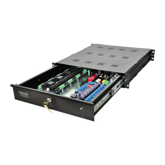
Fully assembled kit includes:
- Trove1R rack enclosure with Altronix/Software House backplane (TSH1R)
- (1) eFlow6NB - Power Supply/Charger
- (1) VR6 - Voltage Regulator
- (1) ACMS8 - Fused Dual Output Access Power Controller
Installation Guide
All registered trademarks are property of their respective owners.
Rev. T1RSH3F8112618
Installing Company: _____________________ Service Rep. Name: __________________________________________
Address: ________________________________________________________ Phone #: _________________________
More than just power.™
Advertisement
Table of Contents

Related Manuals for Altronix Trove T1RSH3F8


Summary of Contents for Altronix Trove T1RSH3F8
-
Page 1: Installation Guide
Access & Power Integration T1RSH3F8 Fully assembled kit includes: - Trove1R rack enclosure with Altronix/Software House backplane (TSH1R) - (1) eFlow6NB - Power Supply/Charger - (1) VR6 - Voltage Regulator - (1) ACMS8 - Fused Dual Output Access Power Controller Installation Guide More than just power.™... -
Page 2: Configuration Chart
Overview: Altronix T1RSH3F8 rack kit is pre-assembled and consist of Trove1SH1R enclosure/backplane with factory installed Altronix power sup- ply/charger and sub-assemblies. This kit also accommodates various combinations of Software House boards for up to eight (8) doors in a single enclosure. - Page 3 1. Remove backplane from enclosure prior to installing into rack cabinet (do not discard hardware). Back of the drawer, 2. In order to mount included UL Listed tamper switch (Altronix Model TS112 or equivalent) turn the enclosure upside down. Punch out the knockout in designated location, on the back viewed from outside.
-
Page 4: Led Diagnostics
LED Diagnostics: eFlow6NB: Red (DC) Green (AC/AC1) Power Supply Status Normal operating condition. Loss of AC. Stand-by battery is supplying power. No DC output. Loss of AC. Discharged or no stand-by battery. No DC output. ACMS8: LED 1- LED 8 (Red) Output relay(s) de-energized. - Page 5 T1RSH3F8: Configuration of Software House Boards: 1. Fasten standoffs onto metal pems configuration (A), (B), or (C) of backplane depending on the access controller (Fig. 5, pg. 5). 2. Position access controller module over corresponding standoffs and fasten screws into standoffs (Fig. 5a, pg. 5). Note: Software House iSTAR Ultra ACM and iSTAR ACM SE/ACM PRO boards have one (1) USB port each.
- Page 6 Notes: - 6 - T1RSH3F8...
- Page 7 Notes: T1RSH3F8 - 7 -...
- Page 8 3.25” 82.3mm Altronix is not responsible for any typographical errors. 140 58th Street, Brooklyn, New York 11220 USA | phone: 718-567-8181 | fax: 718-567-9056 web site: www.altronix.com | e-mail: info@altronix.com | Made in U.S.A. IIT1RSH3F8 B06S MEMBER - 8 -...
Need help?
Do you have a question about the Trove T1RSH3F8 and is the answer not in the manual?
Questions and answers