
Related Manuals for Secura QSF210


Summary of Contents for Secura QSF210
- Page 1 QSF 210 INSTRUCTION MANUAL We’ll Make It Stress-Free If you have any questions along the way, just give us a call. 1-800-359-5520 We’re ready to help! Scan for easy install video san.us/1142...
- Page 2 This mount is NOT compatible. weigh MORE than heavier than the maximum weights indicated may result (11.3 kg) Visit secura-av.com or call 1-800-359-5520 in collapse of the mount and its accessories, causing 25 lbs. (11.3 kg) ? (UK: 0800 056 2853) to fi nd a compatible mount.
-
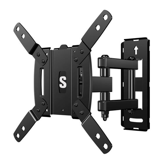
Page 3: Wall Plate
Dimensions TV INTERFACE 7.87in [mm] 200mm .35in 8.8mm 3.94in 100mm 7.87in 200mm WALL PLATE TOP VIEW - EXTENDED SIDE VIEW - EXTENDED 2.80in 16deg DOWN TILT 71mm 10.47in 265.9mm 6.40in 8.15in 162.6mm 207.1mm 30deg 30deg 4deg UP TILT 30° SWIVEL LEFT AND RIGHT WITH AN APPROXIMATE 32" TV SIDE VIEW - RETRACTED FULLY ASSEMBLED MOUNT TOP VIEW - RETRACTED... -
Page 4: Supplied Parts And Hardware
Supplied Parts and Hardware WARNING: This product contains small items that could be a choking hazard if swallowed. Before starting assembly, verify all parts are included and undamaged. If any parts are missing or damaged, do not return the damaged item to your dealer;... - Page 5 STEP 2 Parts and Hardware For concrete installations ONLY Wall Plate Assembly CAUTION : Do not use in drywall or wood Concrete Anchors Fischer UX 10 x 60R Lag Bolt Washers 5/16 in. Lag Bolts 5/16 x 2¾ in. STEP 3 Parts and Hardware Additional Parts and Hardware Allen Key Securement Washer...
- Page 6 STEP 1 Attach TV Bracket to TV 1.1 Measure Your TV Hole Pattern 1.2 Assemble Your TV Bracket Measure the width and height of your TV hole pattern in cm. Determine which TV bracket configuration to use, A, B, or C based on your TV hole pattern measurements.
- Page 7 TV Hole Pattern TV Hole Pattern Measurement Measurement 20.0 20.0 x 20.0 20.0 x 10.0 Dimensions in cm Dimensions in cm 20.0 10.0 20.0 Assemble TV bracket extenders onto TV bracket as illustrated. Assemble TV bracket extenders onto TV bracket as illustrated.
- Page 8 1.3 Select TV Screw Diameter 1.4 Select TV Screw Length Standard configurations are shown. For special If your TV has a flat back, use the shorter screws. applications, or if you Hand thread screws into the threaded inserts on the back of your TV to determine which are uncertain about your Spacers and longer screws are supplied to accommodate: screw diameter...
- Page 9 1.5 Attach TV Bracket Position your TV bracket configuration (A, B, or C) over your TV hole pattern - making sure the bracket is centered over the TV hole pattern and level. CAUTION: Avoid potential personal injuries and property damage! DO NOT use power tools for this step. Tighten the screws only enough to secure the TV bracket to the TV.
- Page 10 STEP 2A Attach Wall Plate to Wall Wood Stud Option CAUTION: Avoid potential personal injury or property damage! ● Drywall covering the wall, must not exceed 5/8 in. (16 mm) ● Minimum wood stud size: common 2 x 4 in. (51 x 102 mm) nominal 1½ x 3½ in. (38 x 89 mm) ●...
- Page 11 Install wall plate assembly using two lag bolts and two washers . Tighten the lag bolts only until the washers pulled firmly against the wall plate assembly NOTE : If needed, you can make small level adjustments to the wall plate assembly by loosening the bottom lag bolt and shifting the wall plate assembly...
- Page 12 STEP 2B Attach Wall Plate to Wall Solid Concrete or Concrete Block Option CAUTION: Avoid potential personal injury or property damage! ● Mount the wall plate assembly directly onto the concrete surface. ● Minimum solid concrete thickness: 8 in. (203 mm) ●...
- Page 13 Insert two anchors CAUTION: Be sure the anchors are seated flush with the concrete surface. Install wall plate assembly using two lag bolts and two washers . Tighten the lag bolts only until the washers pulled firmly against the wall plate assembly CAUTION: Improper use could reduce the holding power of the lag bolt .
- Page 14 STEP 3 Hang TV onto Wall Plate HEAVY! You may need assistance with this step. Position the arm of wall plate assembly so the elbow is bent 90 degrees and pressed against the wall. Hang the TV onto the arm of wall plate assembly by first hooking the top support, then resting the TV into place.
-
Page 15: Manage Cables
Manage Cables If desired, thread a supplied cable tie through the loop provided on the arm of the wall plate assembly , and secure your TV cables along the arm for a clean look. IMPORTANT: Fully extend the arm of wall plate assembly to ensure you have enough slack in the cables for full TV movement. -
Page 16: Tilt Adjustment
TV Adjustments TILT ADJUSTMENT LEVEL ADJUSTMENT Your TV should adjust easily when moved, then stay in place. To adjust the leveling of your TV, loosen the securement screw level your TV, then tighten securement screw If your TV is too loose or too tight, adjust the tilt tension IMPORTANT: This securement screw must be installed to knob by hand. -
Page 17: Removing The Tv
SWIVEL ADJUSTMENT EXTENSION/RETRACTION ADJUSTMENT REMOVING THE TV Your TV should adjust easily when moved, Your TV should adjust easily when moved, HEAVY! You may need then stay in place. then stay in place. assistance with this step. If your TV is too loose or too tight, adjust If your TV is too loose or too tight, adjust To remove your TV from the the arm tension screws using hex key... - Page 18 Features Fully articulating arm with 3 Adjustments allow fi ngertip control pivot points creates optimal of TV or restriction of TV movement viewing positions TV bracket expands to fi t TV hole patterns from 75 x 75 mm up to 200 x 200 mm Level adjustments...
- Page 20 Thank you for choosing Secura! Please take a moment to let us know how we did: Email us: info@secura-av.com Call us: 1-800-359-5520 UK: 0800 056 2853 Milestone AV Technologies and its affi liated corporations and subsidiaries (collectively, “Milestone”), intend to make this manual accurate and complete. However, Milestone makes no claim that the information contained herein covers all details, conditions, or variations.
Need help?
Do you have a question about the QSF210 and is the answer not in the manual?
Questions and answers