Table of Contents
Advertisement
Advertisement
Table of Contents
Troubleshooting

Related Manuals for Vaillant MultiMatic 700/2


Summary of Contents for Vaillant MultiMatic 700/2
- Page 1 Weather compensator multiMATIC 700/2...
-
Page 3: Table Of Contents
Table of contents Table of contents Marketing ...................... 1 System overview ..................2 Controller ....................... 2 Controller classification in accordance with ErP ..........2 Optional accessories ..................3 Scope of delivery ................... 4 Planning and dimensioning ................ 5 Planning requirements ................... 5 3.1.1 Installation locations .................. -
Page 4: Table Of Contents
Table of contents 5.1.4 Installing and connecting the VR 71 module ..........89 Start-up ......................91 5.2.1 Settings in the Installation assistant ............. 91 5.2.2 Settings matrix: System diagram and configuration for the VR 70, VR 71 ... 92 5.2.3 Settings and displays/indicators on the VR 91 .......... -
Page 5: Marketing
700/2 Marketing Please refer to the corresponding marketing presentation for marketing notes and ben- efits. Notes 10/2015 Training 0020228700_00... -
Page 6: System Overview
Menu Op. mode multiMATIC 700/2 The multiMATIC 700/2 is a weather compensator that controls heating, cooling, venti- lation and hot water generation. The eBUS controller is designed for use with products that are equipped with eBUS electronics. Controller classification in accordance with ErP... -
Page 7: Optional Accessories
700/2 Optional accessories VR 70 – mixer and solar module - Can be used with the multiMATIC 700/2 - Expansion to incorporate up to two regulated heating circuits - Expansion to incorporate a solar controller for heating and domestic hot water... -
Page 8: Scope Of Delivery
= Combination possible, but makes no sense = Combination not possible Scope of delivery The following items are contained in the scope of delivery of the multiMATIC 700/2: 1 pc multiMATIC 700/2 1 pc VRC 9535 (DCF) or VRC 693 external sensor... -
Page 9: Planning And Dimensioning
700/2 Planning and dimensioning Planning requirements 3.1.1 Installation locations ● Hanging on an interior wall in the living area. ● Alternative: Installation in the boiler's electronics box Hanging the controller on the wall: The controller should be installed in a place where it can accurately detect the room temperature;... -
Page 10: System Examples
"multi-functional module 2 of 7" (VR 40) accessory unit or, if available, a VR 70 module. Control: Circulation/legionella protection pump: In conjunction with a multiMATIC 700/2, the pump can be programmed to operate at specific times. -
Page 11: Key For System Diagrams And Connection Diagrams
700/2 3.2.3 Key for system diagrams and connection diagrams Item Description Item Description Heat generator Solar pump unit Heat generator pump Solar charging system Swimming pool circulation pump Drinking water station CHP circulation pump Cylinder charging pump Hot water charging pump... - Page 12 700/2 Item Description Item Description VTK solar collector Solar in-line vessel Collecting container Pump, cooling circuit 3-way mixer 3-way mixer, cooling 3-way mixer, passive cooling assembly Fan coil convector Tundish Air collector VWL 10/3 SA outside unit Well pump...
-
Page 13: System Diagrams And Connection Diagrams
700/2 System diagrams and connection diagrams System diagram 1.1 This system diagram does not contain all of the cut-off and safety devices required for correct installation. Comply with the applicable standards and directives. Comply with the necessary minimum circulation water volumes in the heating circuit... - Page 14 700/2 Connection diagram 1.1 Notes 10/2015 Training 0020228700_00...
- Page 15 700/2 System diagram 1.2 This system diagram does not contain all of the cut-off and safety devices required for correct installation. Comply with the applicable standards and directives. Comply with the necessary minimum circulation water volumes in the heating circuit...
- Page 16 700/2 Connection diagram 1.2 Notes 10/2015 Training 0020228700_00...
- Page 17 700/2 System diagram 1.3 This system diagram does not contain all of the cut-off and safety devices required for correct installation. Comply with the applicable standards and directives. Comply with the necessary minimum circulation water volumes in the heating circuit...
- Page 18 700/2 Connection diagram 1.3 Notes 10/2015 Training 0020228700_00...
- Page 19 700/2 System diagram 2 This system diagram does not contain all of the cut-off and safety devices required for correct installation. Comply with the applicable standards and directives. Comply with the necessary minimum circulation water volumes in the heating circuit...
- Page 20 700/2 Connection diagram 2 Notes 10/2015 Training 0020228700_00...
- Page 21 700/2 System diagram 6 This system diagram does not contain all of the cut-off and safety devices required for correct installation. Comply with the applicable standards and directives. Comply with the necessary minimum circulation water volumes in the heating circuit...
- Page 22 700/2 Connection diagram 6 Notes 10/2015 Training 0020228700_00...
- Page 23 700/2 System diagram 7 This system diagram does not contain all of the cut-off and safety devices required for correct installation. Comply with the applicable standards and directives. Comply with the necessary minimum circulation water volumes in the heating circuit...
- Page 24 700/2 Connection diagram 7 Notes 10/2015 Training 0020228700_00...
- Page 25 700/2 System diagram 8.1 This system diagram does not contain all of the cut-off and safety devices required for correct installation. Comply with the applicable standards and directives. Comply with the necessary minimum circulation water volumes in the heating circuit...
- Page 26 700/2 Connection diagram 8.1 Notes 10/2015 Training 0020228700_00...
- Page 27 700/2 System diagram 8.2 This system diagram does not contain all of the cut-off and safety devices required for correct installation. Comply with the applicable standards and directives. Comply with the necessary minimum circulation water volumes in the heating circuit...
- Page 28 700/2 Connection diagram 8.2 Notes 10/2015 Training 0020228700_00...
- Page 29 700/2 System diagram 8.3 This system diagram does not contain all of the cut-off and safety devices required for correct installation. Comply with the applicable standards and directives. Comply with the necessary minimum circulation water volumes in the heating circuit...
- Page 30 700/2 Connection diagram 8.3 Notes 10/2015 Training 0020228700_00...
- Page 31 700/2 System diagram 8.4 This system diagram does not contain all of the cut-off and safety devices required for correct installation. Comply with the applicable standards and directives. Comply with the necessary minimum circulation water volumes in the heating circuit...
- Page 32 700/2 Connection diagram 8.4 Notes 10/2015 Training 0020228700_00...
- Page 33 700/2 System diagram 9 This system diagram does not contain all of the cut-off and safety devices required for correct installation. Comply with the applicable standards and directives. Comply with the necessary minimum circulation water volumes in the heating circuit...
- Page 34 700/2 Connection diagram 9 Notes 10/2015 Training 0020228700_00...
- Page 35 700/2 System diagram 10 This system diagram does not contain all of the cut-off and safety devices required for correct installation. Comply with the applicable standards and directives. Comply with the necessary minimum circulation water volumes in the heating circuit...
- Page 36 700/2 Connection diagram 10 Notes 10/2015 Training 0020228700_00...
- Page 37 700/2 System diagram 11 This system diagram does not contain all of the cut-off and safety devices required for correct installation. Comply with the applicable standards and directives. Comply with the necessary minimum circulation water volumes in the heating circuit...
- Page 38 700/2 Connection diagram 11 Notes 10/2015 Training 0020228700_00...
- Page 39 700/2 System diagram 12 This system diagram does not contain all of the cut-off and safety devices required for correct installation. Comply with the applicable standards and directives. Comply with the necessary minimum circulation water volumes in the heating circuit...
- Page 40 700/2 Connection diagram 12 Notes 10/2015 Training 0020228700_00...
- Page 41 700/2 System diagram 13 This system diagram does not contain all of the cut-off and safety devices required for correct installation. Comply with the applicable standards and directives. Comply with the necessary minimum circulation water volumes in the heating circuit...
- Page 42 700/2 Connection diagram 13 Notes 10/2015 Training 0020228700_00...
-
Page 43: Application Technology
700/2 Application technology Appliance properties The controller is equipped with an illuminated, graphic display. Plain text is used in the display for easy user guidance. Different target room temperatures are set for the heating and set-back phases. -
Page 44: Using The Controller
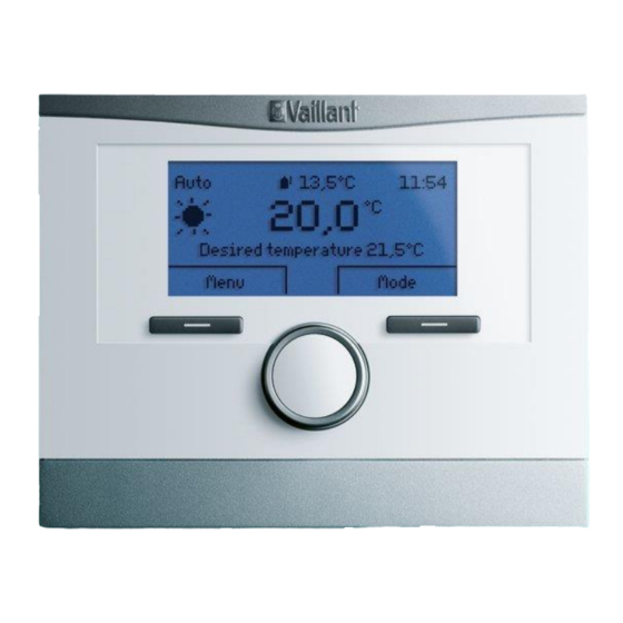
700/2 Using the controller Auto 13.5 °C 11:54 23.0 °C Desired heating temp. 23.0 °C Menu Op. mode Operating and display front panel Diagnostic socket for the competent person Right-hand selection button for "Operating mode" (soft key function) Rotary knob (cannot be pressed) Left-hand selection button for "Menu"... -
Page 45: Displays/Indicators
700/2 Displays/indicators Auto 13.5 °C 11:54 23.0 °C Desired heating temp. 23.0 °C Menu Op. mode Basic display Current outside temperature Current room temperature (only shown for wall-hung installations) Time Current function of the right-hand selection button Current function of the left-hand selection button Desired temperature (target room temperature set) Symbol for heating mode in "Auto"... -
Page 46: Controller Settings
700/2 Controller settings The following information explains the operating concept of the controller. It will show how easy it is to operate the controller, the functions of which are divided up according to the following customer groups: Basic users, technically experienced users and com- petent persons. - Page 47 700/2 4.4.1.2 Setting/changing the operating mode Operating mode Heating Auto Domestic hot water Auto 1 day at home Back Change Operating mode selection menu Pressing the right-hand selection button in the basic display will call up the operating mode menu on the display. This contains setting options to enable the user to operate the system efficiently in different day-to-day situations.
- Page 48 700/2 The settings described below for the operating modes and advanced functions only change the zone that was previously set in the "Configure heating circuit" menu item in the installer level. The setting parameters of any other zones can be accessed via the Menu button.
- Page 49 700/2 Comfort mode This function controls the zone(s) of the heating installation in line with the target room temperature that has been set, without taking the time period into account. The control- ler works using the "Day temperature" that has been set.
- Page 50 700/2 4.4.1.4 Advanced functions Please note that only one advanced function can be used at a time. 1 day at home The function should be enabled if the user spends a day at home outside the usual sequence. The following changes are made: The function activates "Automatic mode"...
- Page 51 700/2 The controller switches off the zone for 30 minutes and the frost protection function is activated. The operating mode that was previously set is reactivated once this time has elapsed. Hot water generation and the circulation pump remain on.
-
Page 52: Basic Controller Configuration (Level 2)
700/2 4.4.2 Basic controller configuration (level 2) General information about reading the following menu trees The menu items with the background contain further information that can be called up by pressing the selection buttons. Information Auto 13.5 °C 11:54 Desired temperatures 23.0 °C... - Page 53 700/2 4.4.2.1 Information The "Information" menu item allows users Information and the competent person to read the sta- tus of all the important values in the sys- System status tem quickly. Consumption If help is required, the user will find the...
- Page 54 700/2 Prompt Select Comment Displays the current target value for the room temperature Day temp. cooling 15.0–30.0 °C during cooling Set-back temp. 5.0 – 30.0 °C Displays the current target value for the room temp. heat. Room temperature Display in °C...
- Page 55 700/2 4.4.2.2 Consumption The "Consumption" menu item is dis- Consumption played only in conjunction with the eco- TEC exclusive …/5 gas-fired wall-hung Current month Heating Electricity boiler, the flexoTHERM heat pump and the VR 71. It allows both the user and the...
- Page 56 700/2 4.4.2.3 Desired temperatures Each of the set temperatures is a "target val- Desired temperatures ue". A wide variety of external influences de- ZONE 1 / 2 / 3 termine whether the selected temperatures for the zones in the control room will be reached.
- Page 57 700/2 ZONE 1 / 2 / 3 Day temp. heating: The temperature that is set applies to: Automatic mode: Within the time periods programmed for a week. Comfort mode, Override mode, "1 day at home" or "Days at home"...
- Page 58 700/2 Domestic hot water The set temperature applies to: Automatic mode: Within the time periods programmed for a week. Comfort mode 4.4.2.4 Time programmes Up to three time windows may be set per day Time programmes or block. The minimum interval is 10 minutes.
- Page 59 700/2 4.4.2.5 Days away from home scheduling This function allows you to set a period and a temperature for an extended absence. You can specify the start and end date and the target room temperature. Hot water generation and the circulation pump are switched off and frost protection is activated.
- Page 60 700/2 4.4.2.7 Basic settings Basic settings Language Date/time Display Costs Offset Operating mode Enter zone name Ventilation Max. room air humidity Default setting Language The following languages can be configured in the controller: DE, GB, FR, IT, DK, NL,...
- Page 61 700/2 Date/time This function enables the current time and date to be set manually. If the controller's external sensor is equipped with a DCF receiver, the controller receives a DCF 77 time signal and sets the date and time automatically.
- Page 62 700/2 Offset room temp. Offset outside temp. The value measured by the sensor is offset by the value that has been set. This com- pensates for external influences on temperature. Adjustment range for room temperature offset: -3.0 to +3.0 K.
-
Page 63: Higher-Level Control Functions
700/2 4.4.2.8 Default setting The factory settings can be reset at two levels: Default setting Time programmes Everything Time programmes If "everything" has been selected, the controller starts by searching for eBUS system components. Everything After resetting to the default setting, the controller automatically calls up the installation assistant. -
Page 64: Sensors
700/2 4.5.2 Sensors If an outside temperature sensor with DCF receiver is connected to the boiler, the date and time are set automatically and the outside temperature is displayed. The temperature sensor integrated in the controller is used for control functions and temperature display in the controller display. -
Page 65: Pump Blocking Protection
1/2, Heating circuit 1/2/3, Zone 1/2/3, Domestic hot water, Buffer cylinder, Solar circuit, Solar cylinder 1, Temperature difference 1 and Ventilation. Depending on the Vaillant accessories used, the scope of the parameters displayed and available for ad- justment varies. - Page 66 700/2 4.5.7.1 System Prompt/setting Select Comment If "Fault list" is displayed, the warning can be Fault status No fault, Fault list found using the "Display" button. Water pressure Display in bars Displays the current heating water pressure. Standby, Heat. mode,...
- Page 67 700/2 Frost protection delay Delays switching on heating mode; relevant in Automatic mode with "Eco" or "Set- back" energy-saving options OT constant heating Lowest outside temperature, from which continuous heating is activated. The non- programmed times are given the target room temperature for the subsequent heating time.
- Page 68 700/2 Adaptive heating curve On the multiMATIC 700/2, there is the option to select an adaptive heating curve ad- justment. This involves the current heating curve being automatically adapted to the system requirements. The multiMATIC 700/2 switches off once the desired room tem- perature has been reached.
- Page 69 700/2 4.5.7.4 Heat generator 1 Prompt/setting Select Comment Standby, Heat. mode, Status Cooling, DHW Displays the flow temperature measured by the flow temperature sensor inside the unit. If an Current flow temp. Display in °C external sensor has been fitted, the tempera- ture it is measuring is displayed here.
- Page 70 700/2 Prompt/setting Select Comment System-dependent assignment of the outside Heating curve 0.1 - 4.0 temperature to the target flow temperature. 15 – 90 °C Minimum temperature Useful when using radiators 15 – 90 °C Maximum temperature Operating behaviour of the heating circuits...
- Page 71 700/2 Type of circuit Setting the type of circuit has an effect on the parameters displayed for the heating cir- cuits, the zones, and on the VRC 700's control strategy. The following provides an overview of which parameters are displayed in the system configuration: Setting Parameters displayed in the "Heating circuit 1/2/3"...
- Page 72 700/2 Excess temperature Setting an increase in the heat requirement for the heat generator, in order to equalise temperature losses caused by long pipes or leaking mixers. Room temp. mod. Temperature modulation: Integration of the current room temperature for adjusting ...
- Page 73 700/2 Heating curve The heating curve and the outside temperature are used as starting points for the basic control function. Both values ensure the flow temperature necessary for the comforta- ble heating of the area. The time programme can be adjusted to ensure that heat is provided at the correct time.
- Page 74 700/2 Auto Off mode Specifies how the heating circuit reacts outside the programmed time period. "Set-back" energy-saving option: The temperature is adjusted to the "Set-back temper- ature" that has been set. This usually reduces the flow temperature outside the pro- grammed time period.
-
Page 75: Domestic Hot Water
700/2 Zone assignment Configuration Setting in installer level Room temp. mod.: None VRC 700 in the unit Zone assignment: Without Room temp. mod.: Temp. mod. or Thermost. possible VRC 700 in the room Zone assignment: VRC700 Room temp. mod.: Temp. mod. or Thermost. possible... - Page 76 700/2 Prompt/setting Select Comment Displayed with diagram = 2, displayed with Charging pump overrun 0 – 10 min VR 70 = 3, 5, 6, or in conjunction with time aroTHERM and flexoTHERM Parallel cyl. charging OFF, ON Cylinder charging The function is started when, in the charging release time, the cylinder value falls be- low the target value by more than 5 K.
- Page 77 700/2 Default setting: No anti-legionella function (owing to risk of scalding). If the "Days away from home" function is activated, the anti-legionella function will not run. Once the "Days away from home" function has ended, the anti-legionella function will run once at 00:00.
- Page 78 Another example of use is for systems in which, for example, only one solid fuel boiler (even a non-Vaillant unit) and the buffer cylinder manager are used to store heat energy in order to avoid having to activate the fossil fuel boiler.
- Page 79 700/2 4.5.7.12 Solar circuit (VR 70 = 6, 12) Prompt/setting Select Comment Collector temperature Display in °C Solar pump status On, Off Solar pump runtime Value in h Reset runtime No, Yes Resets the solar circuit pump operating hours Solar yield sensor Display in °C...
- Page 80 700/2 The solar pump boost/tube collector function ΔT ≤ Switch-off Solar pump optimises measuring of the tube collector hysteresis switches OFF temperature and charging/switching when two cylinders are used. Save collector sensor temperature as refer- When the "solar pump boost" function is acti-...
- Page 81 700/2 the collector sensor is fitted in the immersion sleeve outside the collector and the static pressure of the solar system is set relatively low. In these operating phases the start-up of the solar circuit pump must be securely pre- vented, as otherwise there could be pressure shocks in the system.
- Page 82 700/2 4.5.7.14 Temperature difference 1 (VR 70 = 12) Prompt/setting Select Comment 2 – 25 K Switch-on differential 1 – 20 K Switch-off differential 0 – 99 °C Maximum temperature 0 – 99 °C Minimum temperature TD1 sensor Display in °C TD2 sensor Display in °C...
- Page 83 700/2 Screed-drying function The screed-drying function is used to "heat dry" newly laid heating screed in line with regulations. This function is available for all heating circuits. The flow temperature is adjusted independently of the outside temperature as ...
-
Page 84: Summary Of Level Structure
700/2 4.5.8 Summary of level structure Level 1: Setting the Auto 13.5 °C 11:54 desired temperature 23.0 °C Desired heating temp. 23.0 °C Menu Op. mode Level 2: Information 1 day at home Heating Simple controller configuration Desired temperatures... - Page 85 700/2 Level 2: = Press the selection but- Menu Basic controller configuration System status Fault status Information Consumption Water pressure System status Solar yield Displayed if "Hybrid man- ager" = "triVAI" is selected Collector temperature Environmental yield Displayed if "Cooling...
- Page 86 700/2 Level 2: = Press the selection Simple controller configuration button Days away from home scheduling Days at home scheduling Basic settings Language Date/time Display Display contrast Button lock Preferred display Costs Auxiliary heater Low-tariff elec. rate High-tariff elec. rate...
- Page 87 700/2 Level 3: Installer level Installer level Enter code Service information Enter contact details Service date System System diagram config. Minimum temperature System configuration Fault status System diagram Maximum temperature Water pressure Config.: VR 70 addr. 1 Auto Off mode System status MA VR 70, addr.
- Page 88 700/2 Level 3: Installer level Solar circuit 1 Temperature difference 1 Domestic hot water Collector temperature Switch-on differential Cylinder Solar pump status Switch-off differential Target flow temp. Solar pump runtime Hot water Maximum temperature Current cyl. temp. Reset runtime...
-
Page 89: Installation, Start-Up
Installing the controller in the unit electronics box First check the switch cabinet type: Old type of electronics box: ecoTEC plus unit electronics box with multiMATIC 700/2 Installation: ● Insert the short ends of the three-pin plug con- nector (2) included with the controller into the three horizontal openings on the controller's PCB (1). -
Page 90: Wall-Mounting The Controller
700/2 Integrating multiMATIC 700/2 into the current unit electronics box: Auto 13.5 °C 11:54 Desired heating temp. 23.0 °C Menu Op. mode Schematic diagram showing the built-in multiMATIC 700/2 controller On electronics boxes with vertical plug-in connections and five pins, the blanking cover is removed and then, once the three-pin header has been removed from the controller, the controller is carefully plugged into the slot provided. -
Page 91: Installing And Connecting The Vr 70 Module
700/2 5.1.3 Installing and connecting the VR 70 module The VR 70 accessory may be required depending on the design of the heating installa- tion. It is installed close to the components in the installation using the fastening mate- rial provided. - Page 92 700/2 Overview of VR 70 configurations (1 – 12) VR 70 Assignment of the actuator outputs Assignment of the sensor inputs con- figura- tion DHW1/ Sys- HC1P HC2P DEM1 /Buf Flow Sys- BtDH HC2P LP/3WV TopDHW TopCH Flow HC1P...
-
Page 93: Installing And Connecting The Vr 71 Module
700/2 5.1.4 Installing and connecting the VR 71 module The VR 71 accessory may be required depending on the design of the heating installa- tion. It is installed close to the components in the installation using the fastening mate- rial provided. - Page 94 700/2 Overview of VR 71 configuration Assignment of the sensor inputs Flow DEM1 DEM2 DEM3 DHW1 Assignment of the actuator outputs HC1P HC2P HC3P LP/3WV HC1P Heating pump for heating circuit 1 Close mixer for heating circuit 3 Close mixer for heating circuit 1...
-
Page 95: Start-Up
700/2 Start-up Installation assistant Language System diagram VR 70 1 Adr. 1 config. System configuration * Confirming with "OK" opens the "Installer level > System configuration" menu. The installation assistant has finished and the rest of the installation-specific parameters must now be set here. -
Page 96: Settings Matrix: System Diagram And Configuration For The Vr 70, Vr 71
700/2 5.2.2 Settings matrix: System diagram and configuration for the VR 70, VR 71 Configuration for the VR 70 VR 71 VR 70 Solar hot Solar 2 heating 2 mixed 3 mixed cir- allSTOR water gen- heating circuits circuits... -
Page 97: Settings And Displays/Indicators On The Vr 91
700/2 In the event that a combination of "System diagram" and "VR 70 configuration" is se- lected that is not permitted, the fault message "System diagram selection incorrect" or "VR 70 configuration incorrect" is displayed on the controller. If a combination of "System diagram" and "VR 71 configuration" is selected that is not permitted, the fault message "System diagram selection incorrect"... - Page 98 700/2 Menu tree for VR 91 remote control unit Level 1: Setting the Auto 13.5 °C 11:54 desired temperature 23.0 °C Desired heating temp. 23.0 °C Menu Op. mode Level 2: Information Simple Heating controller configuration Desired temperatures *2, 3...
- Page 99 700/2 = Press the selection button Menu Information System status Fault status Contact details Current room air hum. Serial number Current dew point ZONE 1/2/3 Desired temperatures ZONE 1/2/3 Day temp. heating Day temp. cooling Set-back temp. heat. Time programmes ZONE 1/2/3 *1, °2...
- Page 100 700/2 Installation assistant Language Remote control address Exit installation assistant? Prompt Select Comment DE, GB, FR, IT, DK, NL, ES, TR, HU, RU, Language UA, EE, LV, LT, SE, NO, PL, CZ, HR, SK, RO, SI, KR 1 – 8...
-
Page 101: Maintenance/Troubleshooting
700/2 Maintenance/troubleshooting Maintenance messages Maintenance messages appear on the upper line in the controller's basic display. In the example on the right, the maintenance message has been triggered by the boiler electronics. The following is an overview of the possible maintenance messages. -
Page 102: Fault Messages
700/2 Fault messages If there is a fault, a fault message appears in- stead of the basic display after a brief waiting period. The left button takes you back to the basic display. The fault message remains visible under Menu >... - Page 103 700/2 Message Note/information VR 71 module Faulty eBUS plug connection, cable defective. Communication fault: VR 71 Switching off all relays. S1, S2, S3, S4, S5, S6, S7, S8, S9, S10, S11 sen- Faulty cable, incorrect plug connection, faulty sor fault...
-
Page 104: Sensor Values
700/2 Sensor values VR11 (collector temperature External sensor VR10 (universal sensor) sensor) VR 70, VR 71, boiler, low Unit/Accessories VR 70 loss header, cylinder sensor Temperature Resistance Ω Ω Ω °C 2.076 26.460 95.862 1.976 19.990 72.222 1.862 15.090 54.892... -
Page 105: Additional Troubleshooting Information
700/2 Additional troubleshooting information 6.4.1 Power supply for the VR 70, VR 71 The VR 70 and VR 71 modules have a green LED on the PCB. When this LED is lit up, the module is being supplied with a voltage of 230 V and the internal power supply unit is working. -
Page 106: Appendix
700/2 Appendix Knowledge check What does the multiMATIC 700/2 controller show on its basic display? Which operating modes can be set on a multiMATIC 700/2? Explain the term"Soft key function" used for the two selection buttons! What stages are necessary to modify the target room temperature (desired tem-... - Page 107 (basic display) affects both heating circuits in an in- stallation? With which Vaillant accessories can the multiMATIC 700/2 communicate? Heating circuit: Solar: Cylinder: Remote control: With which heat generator is the multiMATIC 700/2 designed to be used? Wall-hung appliances: Free-standing appliances: Heat pumps: Ventilation units: Notes 10/2015...
-
Page 108: Checklist
700/2 Checklist Settings matrix: System diagram and configuration for the VR 70, VR 71 Configuration for the VR 70 VR 71 VR 70 Solar hot Solar 2 heating 2 mixed allSTOR water gen- heating 3 mixed circuits circuits circuits... -
Page 109: Energy-Saving Tips
700/2 Energy-saving tips Heating using a heat pump If the controller is hanging in the room, the operating mode of the zones should be set to "Day" and the thermostat function should be activated; the auxiliary heater is then required less frequently. - Page 112 All rights reserved. Written or electronic reproduction of this document and extracts thereof requires prior approval. For the installation, always observe the installation and maintenance instructions enclosed with the unit. Planning examples are no substitute for having every single system planned by a professional.
Need help?
Do you have a question about the MultiMatic 700/2 and is the answer not in the manual?
Questions and answers