Sign In
Upload
Manuals
Brands
Vaillant Manuals
Thermostat
MultiMatic 700/2
Vaillant MultiMatic 700/2 Manuals
Manuals and User Guides for Vaillant MultiMatic 700/2. We have
1
Vaillant MultiMatic 700/2 manual available for free PDF download: Product Training
Vaillant MultiMatic 700/2 Product Training (113 pages)
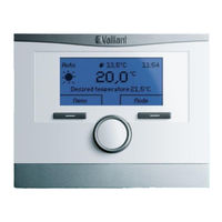
Weather Compensator
Brand:
Vaillant
| Category:
Thermostat
| Size: 7.5 MB
Table of Contents
Table of Contents
3
1 Marketing
5
2 System Overview
6
Controller Classification in Accordance with Erp
6
Optional Accessories
7
VR 71 – Mixer Module
7
VR 91 – Remote Control
7
Possible Combinations of Controllers and Controller Accessories
8
Scope of Delivery
8
3 Planning and Dimensioning
9
Planning Requirements
9
Installation Locations
9
External Sensor
9
System Examples
10
Planning Information
10
Inside the Unit
10
Hydraulics
10
Preliminary Note to the Following System Diagrams
10
Key for System Diagrams and Connection Diagrams
11
System Diagrams and Connection Diagrams
13
Connection Diagram 1.1
14
System Diagram 1.2
15
4 Application Technology
43
Appliance Properties
43
Using the Controller
44
Operating and Display Front Panel
44
Displays/Indicators
45
Basic Display
45
Menu Display
45
Controller Settings
46
Operating Level 1 (Basic User)
46
Setting/Changing the Desired Temperature
46
Setting/Changing the Operating Mode
47
Operating Mode Selection Menu
47
Menu Structure
47
Heating Operating Modes
48
Automatic Mode
48
Eco
48
Set-Back
48
Comfort Mode
49
Set-Back Mode
49
System off Active
49
Frost Protection Function
49
Advanced Functions
50
1 Day at Home
50
1 Day Away from Home
50
Ventilation Boost
50
Party Function
51
Manual Cooling
51
Cylinder Boost
51
Basic Controller Configuration (Level 2)
52
Information
53
System Status
53
Yield/Consumption Display
54
Consumption
55
Current Month/Last Month/History
55
Contact Details
55
Serial Number
55
Desired Temperatures
56
Layout of Zones and Heating Circuits
56
Zone 1 / 2 / 3
57
Day Temp. Heating
57
Day Temp. Cooling
57
Set-Back Temp. Heat
57
Domestic Hot Water
58
Time Programmes
58
Days Away from Home Scheduling
59
Days at Home Scheduling
59
Basic Settings
60
Language
60
Date/Time
61
Display Contrast
61
Button Lock
61
Preferred Display
61
Offset Room Temp.
62
Offset Outside Temp.
62
Operating Mode
62
Enter Zone Name
62
Default Setting
63
Higher-Level Control Functions
63
Automatic Configuration
63
Sensors
64
DCF Signal
64
Energy Manager
64
Chimney Sweep Mode
64
Pump Blocking Protection
65
Installer Level (Level 3)
65
Service Information
65
System Configuration
65
System
66
Frost Protection Delay
67
OT Constant Heating
67
Example for OT Constant Heating
67
Adaptive Heating Curve
68
System Diagram Configuration
68
Additional Module
68
Heat Generator 1
69
Heat Generator 2
69
Heating Circuit 1 / 2 / 3
69
Type of Circuit
71
Excess Temperature
72
Room Temp. Mod.
72
Thermostat Function
72
Heating Curve
73
Auto off Mode
74
"Set-Back" Energy-Saving Option
74
Eco Energy-Saving Option
74
Zone Assignment
75
Cylinder Charging
76
Anti-Legionella Function
76
Cylinder Charging Offset
77
Charging Pump Overrun Time
77
Parallel Cylinder Charging
77
Basic Buffer Cylinder Management
78
Buffer Cylinder
78
Solar Circuit (VR 70 = 6, 12)
79
Basic Function
79
Solar Function
79
Solar Circuit Protection Function
80
Functional Description
81
Solar Cylinder 1
81
Maximum Temperature
81
Temperature Difference 1
82
Ventilation
82
Sensor/Actuator Test
82
Screed-Drying Function
83
Summary of Level Structure
84
5 Installation, Start-Up
89
Installing the Controller in the Unit Electronics Box
89
Old Type of Electronics Box
89
Integrating Multimatic 700/2 into the Current Unit Electronics Box
90
Wall-Mounting the Controller
90
Installing and Connecting the VR 70 Module
91
Terminal Assignment for the VR 70 Module
91
VR 70 Printed Circuit Board
91
Overview of VR 70 Configurations (1 – 12)
92
Installing and Connecting the VR 71 Module
93
Terminal Assignment for the VR 71 Module
93
VR 71 Printed Circuit Board
93
Overview of VR 71 Configuration
94
Assignment of the Sensor Inputs
94
Assignment of the Actuator Outputs
94
Start-Up
95
Settings in the Installation Assistant
95
Settings Matrix: System Diagram and Configuration for the VR 70, VR 71
96
Assignment of System Diagrams to Heat Generators
97
Settings and Displays/Indicators on the VR 91
97
Front View of the VR 91
97
Menu Tree for VR 91 Remote Control Unit
98
6 Maintenance/Troubleshooting
101
Maintenance Messages
101
Fault Messages
102
Sensor Values
104
Additional Troubleshooting Information
105
Power Supply for the VR 70, VR 71
105
Checking the Ebus Power Supply
105
Faulty Ebus Communication
105
No Display, VRC 700 (Built into the Electronics Box) Not Working
105
Blank Display (Controller in Living Room)
105
Knowledge Check
106
7 Appendix
106
Checklist
108
Energy-Saving Tips
109
Advertisement
Advertisement
Related Products
Vaillant multiMATIC VRC 700
Vaillant multiMATIC VRC 700/5
Vaillant multiMATIC VRC 700f/4
Vaillant climaVAIR V 7-085 M3N
Vaillant climaVAIR V 7-075 M3N
Vaillant climaVAIR V 7-060 M2N
Vaillant climaVAIR V 7-050 M2N
Vaillant multiMATIC 700
Vaillant 0020184844
Vaillant 0020242487
Vaillant Categories
Boiler
Water Heater
Heat Pump
Thermostat
Air Conditioner
More Vaillant Manuals
Login
Sign In
OR
Sign in with Facebook
Sign in with Google
Upload manual
Upload from disk
Upload from URL