Table of Contents
Advertisement
Quick Links
Advertisement
Table of Contents

Related Manuals for SimCom SIM8905A


Summary of Contents for SimCom SIM8905A
- Page 1 SIM8905A_User Manual_ V1.00...
- Page 2 Smart Machine Smart Decision Compliance Information: FCC Compliance Statement: This device complies with Part 15 of the FCC Rules . Operation is subject to the following two conditions: 1. This device may not cause harmful interference, and 2. This device must accept any interference received, including interference that may cause undesired operation.
- Page 3 Smart Machine Smart Decision 1. SIM8905A Description 1.1. Summarize SIM8905A is a smart module, which is based on Qualcomm MSM8909 platform. It includes baseband, memory, RF front end and required circuitry to support LTE-FDD. 1.2. Feature Feature Implementation Quad ARM Cortex-A7 cores up to 1.1 GHz...
- Page 4 Smart Machine Smart Decision Voice codec support: G711; Raw PCM; QCELP; EVRC, -B, -WB; AMR-NB, -WB; GSM-EFR, -FR, -HR; Audio codec support: MP3; AAC+, eAAC; AMR-NB, -WB, G.711, WMA 9/10 Pro USIM card Dual cards dual standby LTE Category 4 - 150 Mbps (DL) ...
-
Page 5: Table Of Contents
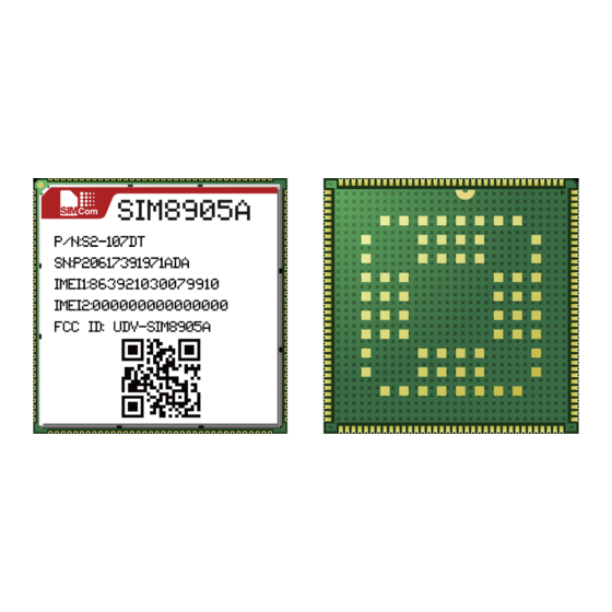
Smart Machine Smart Decision 1.3. Pin ACCL_INT1_N/GPIO_96 VBAT_BB ACCL_INT2_N/GPIO_65 VBAT_BB MAG_INT_N/GPIO_36 ALSP_INT_N/GPIO_94 MIC1P GPIO_98 GND_MIC GPIO_0 MIC2P GPIO_110 EAR_P MIC_BIAS1 GPIO_97 GPIO_68 EAR_M GPIO_69 SPK_P GPIO_89 SPK_M MIC_BIAS2 GPIO_88 GPIO_92 USB_DM GPIO_31 USB_DP KEY_VOL_DOWN_N RESET KEY_VOL_UP_N USB_ID UART2_TXD USIM2_DET UART2_RXD USIM2_RST SIM8905 SENSOR_I2C_SDA... - Page 6 Smart Machine Smart Decision 1.4. Picture Figure 1: Top and Bottom view of SIM8905A...
- Page 7 Smart Machine Smart Decision 1.5. Dimension Figure 2: Dimention...
- Page 8 The power supply pins of SIM8905A include VBAT_RF and VBAT_BB. VBAT_RF directly supplies the power to RF PA; VBAT_BB supplies the power to the baseband system. The power supply of SIM8905A ranges from 3.4V to 4.4V, and 3.9V is recommended. It must be able to provide sufficient current up to 3A for the high-power transmitting.
-
Page 9: Vbat_Bb
Figure 5: DC-DC power supply reference circuit For battery-powered application, the 3.7V lithium battery can be connected to SIM8905A VBAT pins directly, but other types of battery must be used carefully, since their maximum voltage may rise over the absolute maximum voltage of the module. - Page 10 Power on Users can power on SIM8905A by pulling down the PWRKEY pin for more than 2 second then release. This pin is already pulled up to 1.8V internally, so external pull up is not necessary. Reference circuits are shown as below: 1.8V...
- Page 11 Figure9: Timing of power on module Power off Users can power off SIM8905A by pulling down the PWRKEY pin for more than 8 seconds. VRTC VRTC is the power supply for RTC circuit and charger output for coin cell or backup battery. If RTC support is needed when the battery is removed, a qualified coin cell or keep-alive capacitor is required on the VRTC pin.
-
Page 12: Usb_Dm
For SD signals pull-up USIM1_VDD 1.8/2.95 USIM 1 USIM2_VDD 1.8/2.95 USIM 2 LDO17_2V85 2.85 Display, camera, sensors USB Interface SIM8905A provides one High-speed USB 2.0 interface, used for software upgrading, debugging, charging, etc. VBUS USB_VBUS USB_DP USB_DP USB_DM USB_DM USB_ID <1pF Connector Module Figure 13: USB reference circuit In addition, SIM8905A supports OTG function, but external 5V power supply is required. -
Page 13: Gnd
Connector Figure14: USB_OTG reference circuit Linear Battery Charger SIM8905A module integrates a 1.44A linear battery charger for single-cell lithium-ion batteries. Charging Control Battery charging is controlled by a PMIC state-machine. The first step in the automated charging process determines if trickle charging is needed. Charging of a severely depleted battery must begin with trickle charging to limit the current, avoid pulling VDD down, and protect the battery from more charging current than it can handle. -
Page 14: Gpio_98
VBAT_SNS is used for battery voltage sensing, the typical input range is 2.5V~4.5V. UART/SPI/I2C SIM8905A provides several sets of GPIOs which are available as BLSP (BAM-enabled low-speed peripheral) interfaces that can be configured to support various interface combinations, as shown in the following table. The operation voltage is 1.8V... - Page 15 Placed close to SD card Figure17: SD card reference circuit Display Interface SIM8905A provides a 4-lane MIPI_DSI, with 1.5 Gbps per lane high-speed mode bandwidth, to support 720p HD display. PWM is used as PWM control for external WLED driver.
- Page 16 Smart Machine Smart Decision MIPI_DSI_LANE2M MIPI_DSI_LANE2P MIPI_DSI_LANE3M MIPI_DSI_LANE3P If only 2-lane MIPI_DSI is needed, just leave LANE2 and LANE3 floating. Module VBAT LED+ LED+ WLED LED+ driver LED- LED- LED- LCD_ID LDO17_2V85 VCC(2.8V) LDO6_1V8 10 VCC_IO LCD_RST_N 11 RESET LCD_TE 12 TE 13 NC 14 NC...
-
Page 17: Cam1_Rst_N
Smart Machine Smart Decision Camera Interface SIM8905A supports two cameras: 2-lane MIPI_CSI primary camera up to 8MP resolution and 1-lane MIPI_CSI secondary camera up to 5MP resolution. Table 7: Camera interface pin definitions Pin Name Pin# Type Description MIPI_CSI0_CLK_M MIPI_CSI0_CLK_P... - Page 18 CAM0_PWDN 2.2K 2.2K CAM_I2C_SCL CAM_I2C_SDA Figure 19: Primary camera reference circuit Audio SIM8905A provides two microphone inputs and three outputs including earpiece, stereo headphones, and mono class-D speaker driver. Table 8: Audio interface pin definitions Pin Name Pin# Type Description...
- Page 19 Smart Machine Smart Decision Microphone Close to microphone 33pF 10pF MIC1P route as differential pair 33pF 10pF & shielded by GND Electret GND_MIC Microphone 33pF 10pF Module Figure 20: Microphone reference circuit Note: Internal MIC_BIAS pull-up is used to reduce BOM cost and PCB routing. Single-ended capless input is the only supported configuration, but differential routing is recommended.
- Page 20 Figure 21: H eadset reference circuit Note: 1. SIM8905A also supports NO/NC type headset jack with detect pin on HPH_L or GND. 2. HPH has a negative swing and requires a bi-directional TVS diode. Table 10: Headphone output performance specifications...
- Page 21 Smart Machine Smart Decision MΩ Disabled output Measured externally, with amplifier disabled impedance Note: The VDD_CP is internal Voltage of module. Earpiece Class AB earpiece driver supports 10.67 Ω, 16 Ω, 32 Ω, and up to 50 KΩ loads. Its typical output power at 1.02 KHz, 6 dB gain, and THD + N ≤...
- Page 22 Turn on time 10.0 Microphone bias SIM8905A provides two microphone bias outputs: MIC_BIAS1and MIC_BIAS2. The microphone bias cannot be used for ECM-type microphone. MIC_BIAS1and MIC_BIAS2 could be used for External MEMS microphone as power supply. The microphone bias output performance specifications are shown in the following table:...
- Page 23 µF External bypass mode[1] [2] USIM Interface SIM8905A supports dual cards dual standby, and card presence detection. Note: The standard software provided by SIMCom only supports single USIM1 card configuration. Table 14: USIM interface pin definitions Pin Name Pin# Type...
- Page 24 ±1 Vibrator SIM8905A supports silent incoming-call alarms with its vibration motor driver. The vibration driver is a programmable voltage output that is referenced to VBAT; when off, its output voltage is VBAT. The motor is connected between VBAT and the VIB_DRV_N pin. The programmable motor voltage ranges from 1.2 to 3.1 V in...
- Page 25 By default, R1 is 0Ω, C1 and C2 are reserved. The RF connector in Figure 27 is used to ensure the accuracy and convenience of the conduction testing, so SIMCOM suggest keeping it. If...
- Page 26 By default, R1 is 0Ω, C1 and C2 are reserved. The RF connector in Figure 28 is used to ensure the accuracy and convenience of the conduction testing, so SIMCOM suggest keeping it. If...
- Page 27 Smart Machine Smart Decision PCB Layout This section provides PCB layout guidelines for SIM8905A users to ensure their production against lots of issues, and achieve the optimum performance. Stack-up Options At least, 4-layer through-hole PCB should be chosen for good impedance control and signal shielding.
- Page 28 Smart Machine Smart Decision ESD component and bypass caps should be placed closed to USIM Card USIM card signals should be far away from other high-speed signal MIPI_DSI/CSI Protect MIPI_DSI/CSI signals from noisy signals (clocks, SMPS, etc.) Differential pairs, 100 Ω...
- Page 29 Smart Machine Smart Decision External components should be located near the USB connector. Should be routed away from sensitive circuits and signals. If there are test points, place them on the trace to keep branches as short as possible ...
- Page 30 Smart Machine Smart Decision transients Analog output Coplanar ground fill on both sides (of traces or pair as appropriate); in between ground planes – grounds above and below Isolate from noise sources such as antenna, RF signals, SMPS, clocks, and other digital signals with fast transients.
- Page 31 SIM8905E Document Electrical and Reliability Absolute Maximum Ratings Absolute maximum ratings reflect the stress levels that, if exceeded, may cause permanent damage to the device. Functionality and reliability are only guaranteed within the operating conditions. Table 19: Absolute maximum ratings Parameter Unit VBAT...
- Page 32 Smart Machine Smart Decision Digital-logic Characteristics Table 22: 1.8 V digital I/O characteristics Parameter Description Unit High-level input voltage 1.17 Low-level input voltage 0.63 High-level output voltage 1.35 Low-level output voltage 0.45 Table 23: USIM interface characteristics (USIM_VDD=1.8V/2.95V) Parameter Description Unit High-level input voltage 0.7* USIM_VDD...
- Page 33 Smart Machine Smart Decision PWRKEY Characteristics Table 26: PWRKEY characteristics Parameters Description Unit High-level input voltage Low-level input voltage VRTC Characteristics Table 27: VRTC characteristic Parameter Description Unit VRTC VRTC input voltage 3.25 VRTC current consumption RTC-IN VRTC VRTC output voltage -OUT VRTC output current RTC-OUT...
- Page 34 If this discharge path is through a semiconductor device, it may result in destructive damage. SIM8905A must be handled according to the ESD Association standard: ANSI/ESD S20.20-1999, Protection of Electrical and Electronic Parts, Assemblies, and Equipment.
- Page 35 Smart Machine Smart Decision Module Receiving Sensitivity Table 32: Reference sensitivity QPSk P (LTE) REFSENS E-UTRA Duplex 1.4 MHz 3 MHz 5 MHz 10 MHz 15 MHz 20 MHz Band number mode -102.7 -99.7 -93.2 -104.7 -101.7 -100 -95.2 -103.2 -100.2 -101.7 -98.7...
- Page 36 Smart Machine Smart Decision Contact us: Shanghai SIMCom Wireless Solutions Co.,Ltd. Address: Building B, SIM Technology Building, No. 633, Jinzhong Road, Shanghai, P. R. China 200335 Tel: + 86 21 3157 5100 Fax: +86 21 3157 5200 http://simcomm2m.com/ URL: - 36 -...
Need help?
Do you have a question about the SIM8905A and is the answer not in the manual?
Questions and answers