Sign In
Upload
Download
Table of Contents
Contents
Add to my manuals
Delete from my manuals
Share
URL of this page:
HTML Link:
Bookmark this page
Add
Manual will be automatically added to "My Manuals"
Print this page
×
Bookmark added
×
Added to my manuals
Manuals
Brands
Edwards Manuals
Controller
EXC120
Instruction manual
Edwards EXC120 Instruction Manual
Turbomolecular pump controllers
Hide thumbs
1
2
3
4
Table Of Contents
5
6
7
8
9
10
11
12
13
14
15
16
17
18
19
20
21
22
23
24
25
26
27
28
29
30
31
32
33
34
35
36
37
38
39
40
41
42
43
44
45
46
47
48
49
50
51
52
53
54
page
of
54
Go
/
54
Contents
Table of Contents
Bookmarks
Table of Contents
Table of Contents
Introduction
Scope and Definitions
Description
Controls and Indicators (EXC120/300/300M Only)
EXC120 Controller Front Panel
EXC300/300M Controller Front Panel
Bakeout Band Control (EXC120/300/300M Only)
Connection of an Active Gauge
Backing Pump Control (EXC120/300/300M Only)
Logic Interface
Introduction
Electrical Supplies
Control Inputs
Status Outputs
Analogue Outputs
Vent-Valve Control
Vent on Stop
Vent on Fail and Vent on Axial Emergency
Controller Fail Conditions
General
Internal Timer
Axial Emergency (EXC300M Only)
Electrical Connections
Rear Panel of the EXC120 Controller
Rear Panel of the EXC120E Controller
Rear Panel of the EXC300/300M Controller
Technical Data
Operating and Storage Conditions
Mechanical Data
Electrical Data
Electrical Connectors
Factory Settings
EXC120, EXC300 and EXC300M Controller Dimensions (MM)
EXC120E Controller Dimensions (MM)
Installation
Unpack and Inspect
Fit the Controller
Introduction to Controller Electrical Connections
Schematic Diagram of EXC120 & EXC120E Controller Electrical Connections
Schematic Diagram of EXC300 & EXC300M Controller Electrical Connections
Connect the Electrical Supply
Connect Additional Earth (Ground) Bonding (if Required)
Connect the EXT Pump
Connect the Backing Pump (EXC120/300/300M Only)
Connect the Bakeout Band (EXC120/300/300M Only)
Connect an Active Gauge
Direct Operation of the Backing Pump
Operation of the Backing Pump through a Contactor
Connect the Logic Interface to Your Equipment
Adjust the Normal Speed Setpoint
Adjust the Internal Timer
Configure the Controller
Introduction
Enable/Disable the Internal Timer to Monitor Low Pump Speed
Top Cover of the Controller
Vent Options
Operation
Start-Up
Standby
Bakeout Band Control (EXC120/300/300M Only)
Operation with High Inlet Pressure
Operation with High Pump Temperature
The Hours Counter (EXC300 Only)
Normal Shutdown
Automatic Shutdown after Fail Condition
Reset the Controller after Fail Condition
Electrical Supply Failure
Maintenance
Safety
Replace a Fuse
Introduction
Replace the Electrical Supply Fuse
Replace the Bakeout Band Fuse (EXC120/300/300M Only)
Fault Finding
Clean the Controller
Storage and Disposal
Storage
Disposal
Spares and Accessories
Introduction
Spares
Accessories
Pump-To-Controller Cable
BX Bakeout Band (EXC120/300/300M Only)
TAV Vent-Valve
ACX Air-Cooler
Active Vacuum Gauges
Engineering Diagrams
EXC120/120E/300 Controller to EXT Pump Connections
EXC300M Controller to EXT Pump Connections
Active Gauge Connector
Advertisement
Quick Links
1
Controls and Indicators (Exc120/300/300M Only)
2
Logic Interface
Download this manual
Description
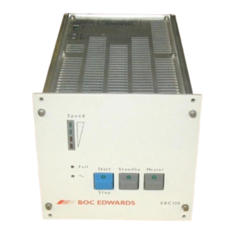
EXC120 Controller
EXC120E Controller
EXC300 Controller
EXC300M Controller
Instruction Manual
EXC Turbomolecular Pump Controllers
D396-14-880
Issue J Original
Item Number
D396-16-000
D396-17-000
D396-14-000
D396-15-000
Table of
Contents
Previous
Page
Next
Page
1
2
3
4
5
Advertisement
Table of Contents
Need help?
Do you have a question about the EXC120 and is the answer not in the manual?
Ask a question
Questions and answers
Related Manuals for Edwards EXC120
Controller Edwards EXC300 Instruction Manual
Turbomolecular pump controllers (54 pages)
Controller Edwards EXC300M Instruction Manual
Turbomolecular pump controllers (54 pages)
Controller Edwards EXC 100E Instruction Manual
Turbo pump controller (42 pages)
Controller Edwards iTIM E73/A1/T1 Instruction
(42 pages)
Controller Edwards Active Gauge Controller Instruction Manual
Rs232 option (41 pages)
Controller Edwards D395-90-000 Instruction Manual
Active digital controller (36 pages)
Controller Edwards 4-NET-TP-HC Installation Sheet
Twisted pair sfp network controller (2 pages)
Controller Edwards AIGX-S-NW25 Instruction Manual
Active ion gauge (26 pages)
Controller Edwards D397-00-000 Instruction Manual
Turbo instrument controller (tic) serial communications (22 pages)
Controller Edwards D395-92-000 Instruction Manual
Turbo and active gauge controller (44 pages)
Controller Edwards CXS Instruction Manual
Control box (16 pages)
Controller Edwards 4-NET-CAT Installation Sheet
100 mbps sfp network controller (2 pages)
Controller Edwards PC2K Manual
Pressure controller kit (98 pages)
Controller Edwards D357-35-000 Instruction Manual
Active strain gauge (24 pages)
Controller Edwards AIGX-D-NW25 Instruction Manual
Active ion gauge (24 pages)
Controller Edwards ASG2-1000-1/8 NPT Instruction Manual
Asg2 series active strain gauge (20 pages)
This manual is also suitable for:
Exc300
Exc120e
Exc300m
Table of Contents
Print
Rename the bookmark
Delete bookmark?
Delete from my manuals?
Login
Sign In
OR
Sign in with Facebook
Sign in with Google
Upload manual
Upload from disk
Upload from URL


Need help?
Do you have a question about the EXC120 and is the answer not in the manual?
Questions and answers