
Related Manuals for Edwards AIGX-S-NW25


Summary of Contents for Edwards AIGX-S-NW25
- Page 1 D048-50-880 Issue E Original Instruction Manual Active Ion Gauge Description Item Number AIGX-S-NW25 D048-50-000 AIGX-S-DN16CF D048-51-000 AIGX-S-DN40CF D048-52-000...
- Page 2 Declaration of Conformity Edwards Limited, Crawley Business Quarter, Manor Royal, Crawley, West Sussex, RH10 9LW, UK declare under our sole responsibility, as manufacturer and person within the EU authorised to assemble the technical file, that the product(s) Active Ion Gauge...
-
Page 3: Table Of Contents
Calibration Service .....................18 STORAGE AND DISPOSAL ............... 19 Storage ........................19 Disposal ........................19 SPARES AND ACCESSORIES ..............21 Introduction ......................21 © Edwards Limited 2013. All rights reserved. Page i Edwards and the Edwards logo are trademarks of Edwards Limited. - Page 4 HAM-LET Group. Swagelok™ is trademark of Crawford Fitting Company. Viton™ is trademark of DuPont Dow Elastomers L.L.C. Page ii © Edwards Limited 2013. All rights reserved. Edwards and the Edwards logo are trademarks of Edwards Limited.
-
Page 5: Introduction
The AIGX requires a 14.5 - 30 V d.c. power supply; it has a 0 to 10 V d.c. analogue output which is related to pressure. The AIGX is compatible with Edwards Controllers. Alternatively, you can use an independent power supply and you can read the output signal with a voltmeter or analogue to digital converter. -
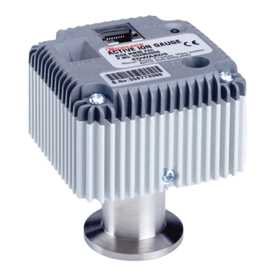
Page 6: General View Of The Aigx (Nw25 Version)
Figure 1 - General View of the AIGX (NW25 version) Electrical connector Filament select switch Set trip switch Status LED Vacuum flange Page 2 © Edwards Limited 2013. All rights reserved. Edwards and the Edwards logo are trademarks of Edwards Limited. -
Page 7: Technical Data
0.7 V to 8.7 V Gauge disabled 9.0 V Emission error 9.5 V Over-pressure trip 9.7 V Minimum load impedance 10 kW © Edwards Limited 2013. All rights reserved. Page 3 Edwards and the Edwards logo are trademarks of Edwards Limited. -
Page 8: Gauge And Degas Enable
0.1 or 1 mA Degas 10 mA Grid voltage Normal 180 V Degas 500 V Filament bias voltage + 30 V Collector voltage Page 4 © Edwards Limited 2013. All rights reserved. Edwards and the Edwards logo are trademarks of Edwards Limited. -
Page 9: Materials Exposed To Vacuum
Stainless Steel and UHV compatible, glass/ceramic Figure 2 - Dimensions (mm) Dim A NW25 85 mm DN16CF 106 mm DN40CF 98 mm © Edwards Limited 2013. All rights reserved. Page 5 Edwards and the Edwards logo are trademarks of Edwards Limited. - Page 10 D048-50-880 Issue E This page has been intentionally left blank. Page 6 © Edwards Limited 2013. All rights reserved. Edwards and the Edwards logo are trademarks of Edwards Limited.
-
Page 11: Installation
A schematic diagram of the recommended electrical connections to the AIGX is shown in Figure © Edwards Limited 2013. All rights reserved. Page 7 Edwards and the Edwards logo are trademarks of Edwards Limited. -
Page 12: Schematic Diagram Of Recommended Electrical Connections
Cable electrical (plug) Degas enable switch Gauge enable switch Back EMF suppression diode (optional) D.C. relay (optional) View of AIGX connector Page 8 © Edwards Limited 2013. All rights reserved. Edwards and the Edwards logo are trademarks of Edwards Limited. -
Page 13: Maximum Cable Length
2.5 V with long cables due to the voltage drop in the supply cable. You should ensure that the signal voltage measurement will operate correctly. © Edwards Limited 2013. All rights reserved. Page 9 Edwards and the Edwards logo are trademarks of Edwards Limited. - Page 14 D048-50-880 Issue E This page has been intentionally left blank. Page 10 © Edwards Limited 2013. All rights reserved. Edwards and the Edwards logo are trademarks of Edwards Limited.
-
Page 15: Operation
V is the measured voltage in volts. Refer to Figure 4. This formula is valid for the range 0.7 V to 8.7 V. © Edwards Limited 2013. All rights reserved. Page 11 Edwards and the Edwards logo are trademarks of Edwards Limited. -
Page 16: Calibration In Different Gases
Table 3 - Gas Calibration Factors for Various Gases Helium Argon 0.75 Neon Krypton Xenon 0.35 Hydrogen Oxygen Carbon Monoxide 1.15 Carbon Dioxide Page 12 © Edwards Limited 2013. All rights reserved. Edwards and the Edwards logo are trademarks of Edwards Limited. -
Page 17: Emission Current
Power on, gauge disabled Green/Amber (alternating) Emissions start-up Green Emission on Green (slow flashing) Degas on Red (flashing) Emission error Over-pressure trip © Edwards Limited 2013. All rights reserved. Page 13 Edwards and the Edwards logo are trademarks of Edwards Limited. -
Page 18: Set-Point Adjustment
Section 5.2 to remove and refit the electronics housing. Ensure that the tube has cooled down before refitting the electronics housing. Page 14 © Edwards Limited 2013. All rights reserved. Edwards and the Edwards logo are trademarks of Edwards Limited. -
Page 19: Separate The Electronics Housing From The Body Tube
D048-50-880 Issue E Figure 5 - Separate the Electronics Housing from the Body Tube Electronics housing Fixing screws Body tube assembly Locating lugs © Edwards Limited 2013. All rights reserved. Page 15 Edwards and the Edwards logo are trademarks of Edwards Limited. - Page 20 D048-50-880 Issue E This page has been intentionally left blank. Page 16 © Edwards Limited 2013. All rights reserved. Edwards and the Edwards logo are trademarks of Edwards Limited.
-
Page 21: Maintenance
If you suspect that the internal fuse has blown, you should check that the voltage and polarity of the electrical supply are correct before replacing the fuse. To replace the fuse refer to Figure 6 and use the following procedure: © Edwards Limited 2013. All rights reserved. Page 17 Edwards and the Edwards logo are trademarks of Edwards Limited. -
Page 22: Calibration Service
Replacement fuses are available from Edwards. Refer to Section 7.2. Calibration Service A calibration service is available for all Edwards gauges. Calibration is by comparison with reference gauges, traceable to National Standards. Contact Edwards for details. Figure 6 - Fuse Replacement Fuse holder... -
Page 23: Storage And Disposal
Equipment, 2002/96/EC. From August 2005, Edwards will offer European customers a recycling service for the AIGX/ cables at the end of the product’s life. Contact Edwards for advice on how to return the AIGX/cables for recycling. © Edwards Limited 2013. All rights reserved. - Page 24 D048-50-880 Issue E This page has been intentionally left blank. Page 20 © Edwards Limited 2013. All rights reserved. Edwards and the Edwards logo are trademarks of Edwards Limited.
-
Page 25: Spares And Accessories
The majority of these centers employ Service Engineers who have undergone comprehensive Edwards training courses. Order spare parts and accessories from the nearest Edwards company or distributor. When ordering, provide the following information: Model and Item Number of equipment. - Page 26 Hex head nut, bolt and washer kit - DN16CF C100-01-630 Annealed copper gasket - DN40CF C100-05-270 Hex head nut, bolt and washer kit - DN40CF C100-05-630 Page 22 © Edwards Limited 2013. All rights reserved. Edwards and the Edwards logo are trademarks of Edwards Limited.
Need help?
Do you have a question about the AIGX-S-NW25 and is the answer not in the manual?
Questions and answers