
Related Manuals for Edwards PGC202


Summary of Contents for Edwards PGC202
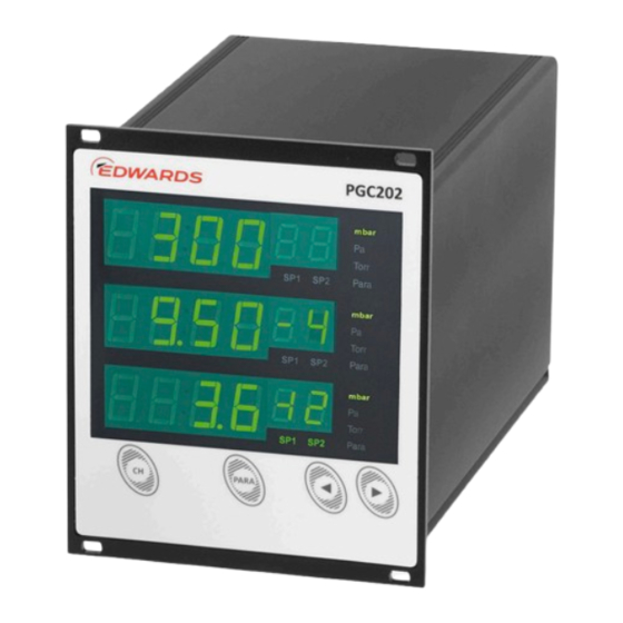
- Page 1 PGC202 PASSIVE GAUGE CONTROLLER INSTRUCTION MANUAL Publication number: D0300041001EN Issue: A Original Instructions edwardsvacuum.com...
- Page 2 IG40 BA DN40CF + D03000210 PRG20K – DN16CF SS D03000310 IG40 EX DN40CF + D03000220 PRG20KCR – NW16 SS D03000410 PGC202 Pirani/Ion Contr +* D03000201 PRG cable 5 m D03000301 IG40 BA/EX cable 5 m bakeable + D03000202 PRG cable 10 m D03000302...
- Page 3 Product Label Meaning This product contains hazardous substances in at least one of the homogeneous materials used which are above the limit PGC202 vacuum requirement in GB/T 26572 as detailed in the declaration table below. gauge controller These parts can safely be used for the environmental protection use period as indicated.
- Page 4 D0300041001EN - Copyright notice Copyright notice © Edwards Limited 2017. All rights reserved. Trademark credits Edwards and the Edwards logo are trademarks of Edwards Limited.
-
Page 5: Table Of Contents
General information ......................3 Key to the symbols ......................3 Basic safety information ....................3 General equipment description PGC202 ..........................5 PRG (Pirani) method of measurement ................5 Principle of measurement for IG (Extractor or Bayard-Alpert) ......... 5 Connectable gauge heads ....................5 Gauge head cables ...................... - Page 6 D0300041001EN - Contents Mechanical installation ....................13 Rack installation ......................13 Front panel installation ....................14 Benchtop instrument ....................15 Connections ........................15 Rear side of the instrument ..................15 Mains connection ...................... 16 Earthing ........................17 PRG measurement channels (PRG 1 and PRG 2) ............17 IG measurement channel (IG) ...................
- Page 7 D0300041001EN - Contents Parameters Switching function parameters (PArA SP) ..............29 Basic terms ........................ 29 Switching functions ....................29 Threshold values ....................29 Lower threshold value (SP1 Lo, SP2 Lo) ............... 29 Upper threshold value (SP1 Hi, SP2 Hi) ..............29 Hysteresis ......................
- Page 8 D0300041001EN - Contents SGC (Set Gas Correction) ................... 45 RSC (Read Sensor Control) ..................45 SSC (Set Sensor Control) .................... 46 RSP (Read Set Point) ....................47 SSP (Set Set Point) ..................... 47 Maintenance and service Maintenance ........................49 General maintenance information ................49 Troubleshooting ......................
- Page 9 D0300041001EN - Contents Supplied equipment ....................13 Display components ....................21 Display in the measurement mode ................. 23 Parameter groups and corresponding parameters ..........26 Available sensor parameters ................... 31 Values for the parameter FIL ................... 31 Values for the parameter unit ................. 34 Values for the parameter AnALoG ................
- Page 10 D0300041001EN - Contents This page has been intentionally left blank. Page vi...
-
Page 11: Description
Based on the technical data please ensure the measuring instrument is suited for the application. Responsibility and warranty Edwards will not assume any responsibility or warranty in cases where the operator or third persons: Do not observe the information given in this document. -
Page 12: Shipping Damage
Remove all of the packaging material and check the instrument. If the instrument is damaged, follow the Edwards return of equipment procedures that are laid out in the back of this manual. Do not use the instrument if it is damaged. -
Page 13: Safety
D0300041001EN - Safety Safety General information The Edwards PGC202 controller is delivered ready for operation. This manual provides installation, operation and maintenance instructions for the PGC202. The instrument must be used as specified in this manual. Key to the symbols Important instructions relating to technical safety and safe operation are emphasised by symbols. - Page 14 D0300041001EN - Safety This page has been intentionally left blank. Page 4...
-
Page 15: General Equipment Description
15 full decades from 1 x 10 mbar to atmospheric pressure is possible. Six switching thresholds permit the integration of the PGC202 within complex vacuum control facilities. The two PRG channels are immediately active upon powering up. -
Page 16: Gauge Head Cables
D0300041001EN - General equipment description Gauge head cables Table 3 Gauge head cables Gauge head type Product description Item number D03000201 10 m D03000202 Gauge head cables PRG 20 m D03000203 30 m D03000204 50 m D03000205 D03000301 Bakeable (up to 200 °C) gauge 10 m D03000302 head cables to IG... -
Page 17: Technical Data
D0300041001EN - Technical data Technical data General data Mechanical data Dimensions: Width: 106.4 mm Height: 128.4 mm Depth: 185.0 mm 1.4 kg Weight: 280 mm approximately (including connected plugs) Installation depth: Usage: Rack installation Front panel installation Benchtop instrument Figure 1 Dimensions (mm) Page 7... -
Page 18: Standard Parameters (Factory Defaults)
D0300041001EN - Technical data Standard parameters (factory defaults) Sensor dependent parameters Table 5 Switching parameters, factory defaults PRG setting IG setting Parameter Parameter description (mbar) (mbar) . . Switching thresold 1 - lower threshold .... -
Page 19: Standards
D0300041001EN - Technical data Standards Conformity with respect to Low Voltage Directive 2014/35/EU Conformity with respect to EMC Directive 2014/30/EU Conformity with respect to RoHS Directive 2011/65/EU Conformity with respect to WEEE Directive 2012/19/EU International/national standards as well as specifications: DIN EN 61010-1 (2011) (Safety requirements for electrical equipment for ... -
Page 20: Ig Measurement Channel
D0300041001EN - Technical data IG measurement channel Extractor (IG40 EX) Bayard-Alpert (IG40 BA) 2 x 10 to 1 x 10 2 x 10 to 1 x 10 mbar Measurement range: mbar ± 2% of measured ± 2% of measured value, Measurement accuracy: value, ±... -
Page 21: Switching Functions / Relay Outputs
D0300041001EN - Technical data Switching functions / relay outputs Switching function relay Number: Assignment: 2 per channel Response time: < 50 ms Adjustment range: IG40 EX 1 x 10 to 1 x 10 mbar IG40 BA 1 x 10 to 5 x 10 mbar PRG 5 x 10 to 5 x 10... -
Page 22: External Control
D0300041001EN - Technical data Measurement channel 1.0 V d.c./decade (0 V ≙ 1 x 10 1.0 V d.c./decade (0 V ≙ 1 x 10 mbar) mbar) U[V] U[V] p = 10 mbar · 10 p = 10 mbar · 10 U[V] U[V] p = 10... -
Page 23: Installation
Install the instrument or locate it so the operator is in a position to operate the mains power switch or ensure that the instrument can be de-energised at any time. Rack installation The PGC202 has been designed for installation within a sub-rack (19", 3 U) in accordance with DIN EN 60297 (IEC 60297) (see Figure 2). -
Page 24: Front Panel Installation
D0300041001EN - Installation Figure 2 Rack installation Attach the sub-rack within the rack. Push the PGC202 into the sub-rack. Affix the instrument to the sub-rack with the neck collar screws and the plastic sleeves supplied with the product. -
Page 25: Benchtop Instrument
Benchtop instrument WARNING: When using the PGC202 as a benchtop instrument fit the two edge protection rubber pieces onto the top and bottom edge of the front panel to avoid injury by sharp edges. When intending to use the PGC202 as a benchtop instrument, then proceed as follows: Push one of the two edge protection rubber pieces supplied with the product over the ... -
Page 26: Mains Connection
D0300041001EN - Installation Figure 5 Rear panel of the instrument Control signal connection for IG gauge head (IG) Ground connection (protective earth) and shield of the PRG measurement cables Measurement signal connection for IG gauge head (IG) Connections for the PRG gauge heads (PRG 1, PRG 2) Connection for the RS232 or RS485 interface Mains connection with mains switch and fuses Connection for analog output and external control... -
Page 27: Earthing
CAUTION: Gauge heads which have not been designed to be operated in connection with the PGC202 or which do not comply with current EMC guidelines can impair operation of the instrument or even damage it. Always operate the PGC202 with approved gauge heads, see Connectable gauge heads. -
Page 28: Control Signals
5, item 3). Affix the touch protection component to the BNC plug on the IG cable after it is connected to the PGC202 and before the PGC202 is switched on. The touch protection component is supplied together with the gauge head cable. -
Page 29: Connecting
Connecting: Connect the peripheral components using a shielded connecting cable to the connection Analog Output/Extern Control on the rear of the PGC202. RS232 / RS485 Interface (Interface RS232 / RS485) CAUTION: When using the RS232 serial interface, use a serial extension cable with a 9-way plug and a 9-way socket. -
Page 30: Relay Output
D0300041001EN - Installation Relay output WARNING: Voltages exceeding 60 V d.c. or 30 V a.c. are dangerous when touched. The operator may only switch output voltages of up to 30 V d.c. or 30 V a.c. with a maximum current of 1 Amp at the connector marked Relay Output. -
Page 31: Operation
Do not use the PGC for safety critical applications. The PGC is not intended to be fail safe. Front panel Figure 10 shows the front panel of the PGC202. Figure 10 Front panel Display of channel 1 with two corresponding switching thresholds... -
Page 32: Control Pushbuttons
'DOWN' ( ) and 'UP' ( Switching on and off Switching on Switch the instrument on at the mains switch. After switching on, the PGC202 runs the following: Self test Display test Display of the software version used ... -
Page 33: Operating Modes
D0300041001EN - Operation Operating modes The PGC202 may be operated in one of the following operating modes: Measurement mode The measurement mode is the standard operating mode. Here the measured values or status messages are displayed (see Measurement mode). Parameter mode In the parameter mode, the operator has access to different parameters. -
Page 34: Measurement Channel Selection
D0300041001EN - Operation Measurement channel selection Press the pushbutton (CH). The instrument selects the next measurement channel. The Para indicator for the selected measurement channel will flash for 10 seconds. Parameter mode selection Press the pushbutton (PARA) and keep it depressed for approximately 2 seconds. ... -
Page 35: Prg Adjustment
D0300041001EN - Operation PRG adjustment Ageing and contamination of the sensor filament will impair the accuracy of the pressure readout. For this it is recommended that the PRG gauge head is adjusted as required. For this, the gauge head must be orientated in the same way in which it is subsequently operated. The adjustment process is performed as follows: Vent the vacuum system and adjust the 100% potentiometer on the PRG gauge head ... -
Page 36: Parameter Mode
D0300041001EN - Operation Parameter mode Selection By pressing the (PARA) pushbutton for approximately 2 seconds the instrument changes from the measurement mode to the parameter mode. The Para indicator comes on for the channel selected in each case. When the instrument is running in the parameter mode and if no pushbutton is operated for 10 seconds, then the instrument will automatically return back to the measurement mode. -
Page 37: Sensor Parameters (Para Sen)
D0300041001EN - Operation Sensor parameters () These parameters affect only the selected measurement channel. Two switching functions are available per measuring channel. Sensor parameters (PArA SEn). General parameters () With the aid of these parameters the instrument can generally be configured. The parameters apply to all measurement channels. - Page 38 D0300041001EN - Operation This page has been intentionally left blank. Page 28...
-
Page 39: Parameters
Basic terms Switching functions The PGC202 contains 6 switching function relays, that is, the switching functions 1 and 2 are available for each measurement channel. These switch depending on the measured pressure. The contacts of the relays are floating and may be used for switching purposes through the... -
Page 40: Configuring The Switching Functions
D0300041001EN - Parameters Figure 14 Behaviour of a switching function in response to pressure changes Pressure Time Normally open contact Common contact Normally closed contact The range between the lower and the upper threshold value produces a certain amount of hysteresis between switching on and switching off of the relay. -
Page 41: Sensor Parameters (Para Sen)
D0300041001EN - Parameters Sensor parameters () A separate set of sensor parameters exists for each measurement channel. Depending on which transmitter is connected to the respective measurement channel, different parameters are available (see Table 12). Table 12 Available sensor parameters ... -
Page 42: Type Of Gas Correction Ig (Gasie)
D0300041001EN - Parameters type of gas in each case. The characteristic may be selected for a gauge head between nitrogen () or argon (). For this proceed as follows: Select the parameter Press the pushbutton (PARA). The setup characteristic is displayed. -
Page 43: Sensor Switch-On Value (T-On)
D0300041001EN - Parameters Sensor switch-on value () This parameter will only appear when the sensor switch-on time has been set to or (see Sensor switch-on type (S-on)). Through the parameter the operator can define a switch-on value. When the pressure in the respective measurement channel drops below the switch-on value, the gauge head is switched on. -
Page 44: Sensitivity Setting For Ig Gauge Head (Sens)
The unit of measurement is indicated on the display (Figure 10). Analog output () Analog output for the gauge heads. Table 15 Values for the parameter Display Description Alternate mode (see Analog output) PGC202 mode (see Analog output) Page 34... -
Page 45: Display Format (Digit)
D0300041001EN - Parameters Display format () Number of digits on the display. Table 16 Values for the parameter Display Description 2 digits, for example 2.5 2 digits, for example 2.47 Display brightness () Display brightness. Table 17 Values for the parameter Display Description ... - Page 46 D0300041001EN - Parameters This page has been intentionally left blank. Page 36...
-
Page 47: Interface (Rs)
D0300041001EN - Computer interface Computer interface Basics Connection The PGC202 can communicate with the computer through a serial interface. RS232 and RS485 interfaces are available. The selection is made through the parameter group in the parameter mode (see General parameters (PArA GEn)). -
Page 48: Communication
D0300041001EN - Computer interface Communication Protocol The following log is used for communication: 8 data bits no parity bit 1 stop bit The baud rate is selectable. 9600 19200 38400 No hardware handshake is used. The messages are transferred by way of ASCII strings. A comma (0x2C) in the string is taken as a separating character. -
Page 49: Command Set (Mnemonics)
D0300041001EN - Computer interface Command set (mnemonics) Command overview Table 22 Mnemonics for read commands Read commands Description Read Pressure Value. Read the pressure value for a measurement channel. Read Version Number Read the instrument software version number. Read Setpoint Status Read the status of the switching thresholds for a channel. -
Page 50: Rpv (Read Pressure Value)
D0300041001EN - Computer interface Table 24 Mnemonics for read and write commands (continued) Read and write commands Description Set Sensor Control Set type of sensor control for a measurement channel. Read Setpoint Read switching thresholds for a channel. Set Setpoint Set switching thresholds for a channel. -
Page 51: Rvn (Read Version Number)
D0300041001EN - Computer interface RVN (Read Version Number) Reading the version number of the instrument software. Example: RVN<CR> Response: x.xx<CR> Parameter Description x.xx Version number RSS (Read Setpoint Status) Reading the status of the switching thresholds for a channel. Example: RSS[a]<CR> Response: b[,][TAB]c<CR>... -
Page 52: Sdg (Set Degas On/Off)
D0300041001EN - Computer interface SDG (Set Degas on/off) Start or terminate degas function. Example: SDG[a, b]<CR> Response: OK<CR> Parameter Description Channel number 1 = Channel 3 (IG) Degas on/off 0 = off 1 = on SKL (Set Key Lock on/off) Switching the key lock on or off. -
Page 53: Ssa (Set Serial Address)
Description Unit 0 = mbar 1 = Pa 2 = Torr Analog output 0 = Legacy controller mode 1 = PGC202 default Number of displayed digits 0 = 2 1 = 3 Brightness 0 = high 1 = low Baud rate... -
Page 54: Sgp (Set General Parameter)
1 = Pa 2 = Torr X = Parameter remains unchanged Analog output 0 = Legacy controller mode 1 = PGC202 default X = Parameter remains unchanged Number of displayed digits 0 = 2 1 = 3 X = Parameter remains unchanged... -
Page 55: Rgc (Read Gas Correction)
D0300041001EN - Computer interface RGC (Read Gas Correction) Reading the type of gas correction factor for a measurement channel. Example: RGC[a]<CR> Response: b<CR> Parameter Description Channel number 3 = Channel 3 (IG) Gas type correction factor channel Format X.XX with a range from 0.20 to 8.00 SGC (Set Gas Correction) Setting the type of gas correction factor for a measurement channel. -
Page 56: Ssc (Set Sensor Control)
D0300041001EN - Computer interface Parameter Description Sensor switch-off type channel 0 = Manual 1 = External 2 = Self-monitoring 3 = Through channel 1 4 = Through channel 2 x.xxxxE±xx Switch-on value in the current unit of measurement x.xxxxE±xx Switch-off value in the current unit of measurement SSC (Set Sensor Control) Setting the type of sensor control for IG. -
Page 57: Rsp (Read Set Point)
D0300041001EN - Computer interface RSP (Read Set Point) Reading the switching thresholds for a channel. Example: RSP[a]<CR> Response: b[,][TAB]c[,][TAB]d[,][TAB]e<CR> Parameter Description Channel number 1 = Channel 1 (PRG 1) 2 = Channel 2 (PRG 2) 3 = Channel 3 (IG) ... - Page 58 D0300041001EN - Computer interface This page has been intentionally left blank. Page 48...
-
Page 59: Maintenance And Service Maintenance
For external cleaning please use a piece of dry cotton cloth. Do not use any aggressive or abrasive detergents. Troubleshooting Fault finding A malfunction of the PGC202 is indicated by an error message on the display (seeError messages). Error messages... -
Page 60: Help The Case Of Faults
Repair Send defective products for repair to the nearest Edwards service office. Edwards will not assume any responsibility or honour a warranty if the operator or third persons have attempted repair work on the PGC202. -
Page 61: Storing And Waste Disposal
D0300041001EN - Storing and waste disposal Storing and waste disposal Storing Return the PGC202 to its protective packaging and store in clean dry conditions until required for use. Do not exceed the storage temperature conditions specified in Environment. Disposal Dispose of the PGC202 and any components safely and in accordance with all local and national safety and environmental requirements. - Page 62 D0300041001EN - Storing and waste disposal This page has been intentionally left blank. Page 52...
- Page 63 Download the latest documents from www.edwardsvacuum.com/HSForms/, follow the procedure in HS1, fill in the electronic HS2 form, print it, sign it, and return the signed copy to Edwards. Note: If we do not receive a completed HS2 form, we will not accept the return of the...
- Page 64 edwardsvacuum.com...
Need help?
Do you have a question about the PGC202 and is the answer not in the manual?
Questions and answers