ITRON RB 4000 Instruction Manual
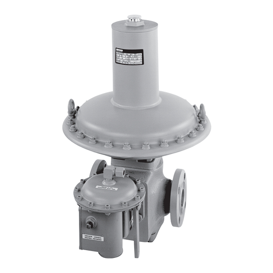
Gas pressure regulator
Hide thumbs
Also See for RB 4000:
- Installation and start-up instructions (5 pages) ,
- Instruction manual (24 pages)

Related Manuals for ITRON RB 4000


Summary of Contents for ITRON RB 4000
- Page 1 Gas Pressure Regulator Gasdruckregelgerät RB 4000 3400992804 Instruction manual Betriebsanleitung w w w . i t r o n . c o m...
-
Page 2: Table Of Contents
Table of Contents EU Declaration of Conformity � � � � � � � � � � � � � � � � � � � � � � � � � � � � � � � � � � � � � � � 3 Description/technical features �... -
Page 3: Eu Declaration Of Conformity
Itron G mbH, H ardeckstrasse 2 , D -‐75185 K arlsruhe declares u nder h is s ole r esponsibility, t hat t he G as p ressure r egulator ... -
Page 4: Description/Technical Features
RB 4000 regulator� Inlet pressure p up to 19 bar umax: The RB 4000 pressure regulator is designed for Outlet pressure range wd: gas supply networks, district station regulation, • DN 25 10 mbar to 2�5 bar industrial service regulation, and all applications •... -
Page 5: Sectional View
Sectional view Fig 1 - RB 4000 sectional view Breather Adjustment screw Loading spring Actuator Diaphragm Anti-pumping valve Sensing line Valve disc Valve seat Fig 2 - RB 4000 with built-in safety shutoff valve Sensing line Safety Shutoff valve (SSV... -
Page 6: Spring Ranges
Outlet Pressure Range DN 25 Spring Characteristic Spring Range Spring Code Colour 4010/11/12 4020/21/22 4030/31/32 (mm) (mm) (mm) (ø 360) (ø 220) (ø 220/TR) 20567075 3�5 15�5 Yellow 18 - 27 mbar • • 20567076 3�5 10�75 25 - 33 mbar •... -
Page 7: Ssv 8500: Description, Resetting
SSV 8500 (for RB 4000 models with integrated SSV 8500) Operating principle of the shut-off valve sure value in the control chamber 5, that from the downstream pipe flow into this chamber through The shut-off device is a safety device that goes... - Page 8 Resetting of the shut-off valve – screw it upside down into the stem 28 until in comes into contact with the cover (fig�b) The shut-off valve must be reset only after having – continue to screw it slowly: with this operation verifying the reason for the intervention and after (by-pass) pressure fills the downstream pipe having re-established normal conditions of work,...
-
Page 9: Ssv 8600: Description, Resetting
SSV 8600 (for RB 4000 models with integrated SSV 8600) Shut-off valve with lever reset (SSV 8600) ing from its balancing position the diaphragm as- sembly 6; as a consequence the control lever 3 This device consists of a valve body 1, a pressure triggers, releasing the stem-valve plug assembly 4�... - Page 10 Resetting of the shut-off valve with lever – when the pressure indicated on the manometer reset (type SSV 8600) is stabilised, continue to move the lever 27 in order to permit the connection of the control – close the downstream stop valve lever 24;...
-
Page 11: Installation
Installation actuator downwards or vertical installation are also possible. • Check that the maximum inlet pressu- re is not higher than the design pressu- Fig 4 gives a typical example of installa- re of the regulator. tion: • The downstream vent valve eases •... - Page 12 Installation with safety systems Pipework should be made to prevent impurities and condensates from collecting and obstructing the passage of the gas. Pipework slope upwards from the The SSV must have a dedicated sensing pressure tap is recommended - see Fig 3. line, whose point of sensing provides a representative pressure.
- Page 13 Fig 4 - RB 4000 with built-in SSV - Installation example Breather lines Vent lines Vent valve Safety relief valve = 5 x DN Fig 5...
-
Page 14: Regulator Start-Up
Regulator Start-up Monitor Start-up After the pressure regulator has been The same procedure must be followed installed, make sure that the on/off valve when starting a monitor and active sy- upstream and downstream and the vent stem, bearing in mind that the pressure valve are all closed. -
Page 15: Maintenance
Maintenance Disassembly The maintenance operations required for Check the following before beginning any the pressure regulator (and the safety shu- disassembly operations on the pressure re- toff valve) are closely linked to the quality of gulator: gas supplied (in terms of moisture content, •... -
Page 16: Eu Konformitätserklärung
Itron G mbH, H ardeckstraße 2 , D -‐75185 K arlsruhe erklärt h iermit i n a lleiniger V erantwortung, d ass d as G asdruckregelgerät ... -
Page 17: Beschreibung/Technische Daten
Betriebsunterhaltung der Baureihe RB 4000 Maximaler Eingangsdruck p bis 19 bar umax Das RB 4000 Gasdruckregelgerät ist für unter- Ausgangsdruckbereich wd: schiedlichste Anwendungen in der Gasversor- • DN 25 10 mbar bis 2,5 bar gung entwickelt, wie Verteilerstationen, Bezirks- •... -
Page 18: Schnittbild
Anti-pumping Impuls- valve dämpfung Sensing line Messleitung Ventilteller Düse Valve disc Valve seat Fig 2 - RB 4000 with built-in safety shutoff valve Fig 2 – RB 4000 mit integriertem SAV Sensing line Messleitung Safety Shutoff valve (SSV Sicherheitsabsperrventil (SAV) -
Page 19: Federbereiche
Ausgangsdruckbereich DN 25 Feder Eigenschaften Federbereich Feder Nr. Farbe 4010/11/12 4020/21/22 4030/31/32 (mm) (mm) (mm) (ø 360) (ø 220) (ø 220/TR) 20567075 3�5 15�5 gelb 18 - 27 mbar • • 20567076 3�5 10�75 25 - 33 mbar • • 20567662 4�5 weiß... -
Page 20: Sav 8500: Beschreibung, Wiedereinrasten
200 – 500 200 – 500 90 – 250 90 – 250 SAV 8500 (für RB 4000 Ausführung mit integriertem SAV 8500 Funktionsprinzip des Sicherheitsabsperrventiles niveau im Vergleicherraum 5, welcher durch die Messleitung 14 mit Ausgangsdruck versorgt wird, Das SAV schließt, wenn das Druckniveau hinter den eingestellten SAV Wert über- oder unter-... - Page 21 Wiedereinrasten des SAV - Schraube die Kappe über Kopf auf die Ventil- stange 28 bis diese am Gehäuse anliegt (Fig� b) Das SAV darf nur wiedereingerastet werden, wenn - Langsam weiter hereindrehen: dadurch wird der vorher der Grund für das Auslösen überprüft ist Druckausgleich am Ventil hergestellt und der und die normal Betriebsbedingungen wieder her- Ausgangsbereich gefüllt...
-
Page 22: Sav 8600: Beschreibung, Wiedereinrasten
SAV 8600 (RB 4000 Ausführung mit integriertem SAV 8600) SAV mit Rückstellhebel (SSV 8600) sprechwerte wird die Position der Membraneinheit 6 verändert, das Schaltgetriebe 3 löst aus und die Dieses Gerät besteht aus Ventilkörper 1, Messwerk Ventiltellereinheit 4 wird geschlossen� Aufgrund... - Page 23 Öffnen des SAV mit dem Öffnungshebel was durch ein installiertes Manometer im Aus- (Typ SAV 8600) gangsrohr überwacht werden kann� – sobald der Druck im Ausgang konstant steht – Schließen der Ausgangs-Absperrarmatur wird durch die weitere Bewegung des Öff- – langsames Öffnen des Rückstellhebels 27 im nungshebels 27 die Verriegelung mit dem Uhrzeigersinn, bis der interne Druckausgleich Schaltgetriebe 24 in Offenstellung erreicht�...
-
Page 24: Einbau Anleitung
Ausgangsdruck > 200 mbar 20 – 40 m/sec überschreiten 35 Nm 55Nm 85 Nm 170 Nm Wir empfehlen die Geräte in horizontaler Leitung mit dem Membrangehäuse nach oben zu instal- lieren� Einbaulagen mit Membrangehäuse nach unten oder in vertikalen Leitungen sind anteilig möglich (ggf� Rücksprache mit Itron) - Page 25 In der Ausgangsleitung empfehlen wir Druckanschlüsse nach Fig 3 Messleitung Verschraubung Einschweißmuffe Horizontale Achse Figure 3 Fig� 3 3400992804 20.07.2009 13:19 Uhr Seite 9 Fig� 4 – RB 4000 mit integriertem SAV – Installationsbeispiel Atmungsleitung Abblaseleitung Abströmventil = 5 x DN Abblaseventil...
-
Page 26: Inbetriebnahme
Inbetriebnahme des Regelgerätes gerät, der in der Lage ist, die festen und flüssigen Bestandteile aufzuhalten, die ansonstendie Funk- Nach Einbau des Regelgerätes bitte prüfen, dass tion des Gerätes beeinflussen könnten� Eingangs-, Ausgangs- und Abströmventil ge- Unbedingt sicherstellen, dass das Gerät komplett schlossen sind�... - Page 27 Fig 8 - Setting key / Justierschlüssel Fig 8 - Setting key Setting key Setting key / Justierschlüssel Adjustment Adjustment screw / screw Justier- schraube The setting key - ref. 20231000 - is provided on request. It may be kept into The setting key –...
- Page 28 Tool A / Werkzeug A UNI 6745-70 / Werkzeug B Tool C O Ring removing tool / UNI 6733-70 / O Ring Ausbringer Werkzeug C Itron GmbH Hardeckstraße 2 76185 Karlsruhe Tel� +49 721 5981 0 info�karlsruhe@itron�com · www�itron�com Fax +49 721 5981 189...
Need help?
Do you have a question about the RB 4000 and is the answer not in the manual?
Questions and answers