
Subscribe to Our Youtube Channel
Related Manuals for Kauai Labs VMX-pi

Summary of Contents for Kauai Labs VMX-pi
- Page 1 VMX-pi Robotics Controller/Motion & Vision Processor User's Guide Kauai Labs Copyright — 2019...
-
Page 2: Table Of Contents
Analog Inputs CAN Bus Monitor CAN TX Loopback Digital Inputs Digital Outputs Encoders Interrupts PWM Generation Real-time Clock (RTC) UART VMX-pi Configuration RoboRIO (FRC) Field-Oriented Drive Rotate to Angle Straight-line Driving Automatic Balancing Collision Detection Motion Detection Data Monitor Guidance... - Page 3 Terminology Gyro/Accelerometer Calibration Magnetometer Calibration Support Support Forum Updating Firmware Factory Test Procedure Advanced USB Serial Protocol navXUI Customization Technical References...
-
Page 4: Overview
VMX-pi transforms your Raspberry Pi into a reliable, real-time Robotics Controller or Vision/Motion Processor with embedded IMU & CAN-bus interface. VMX-pi plus Raspberry Pi can perform both real-time robotic control and higher-layer Robot Position Tracking, Drivetrain path-planning and kinematics-based control –... -
Page 5: Features
Network Time Server w/Battery-backed Real-time clock for synchronizing data and logs on distributed networked robot controllers Additional Key Features: Write code directly on VMX-pi: Functions either as a standalone Development System (via Raspberry Pi inputs for keyboard, mouse, HDMI monitor), or can be used with a remote development environment... - Page 6 Overview Features Raspberry PI host enables high performance Automatic current-limiting ensures Raspberry Pi is powered even when external devices (or short-circuits) exceed current limits External Device Power Management Selectable 5V or 3.3V Power Supply for external sensors and devices, up to .5A Voltage Translation for signals to/from 5V and 3.3V external sensors and devices IMU with Sophisticated Motion Processing High Accuracy, Low-latency Yaw, Pitch and Roll Angles, w/update rate from 4-200Hz...
-
Page 7: Technical Specifications
VMX-pi circuit board must be held still. Additional details can be found in the VMX-pi-datasheet. Additionally, the specifications for the connector cables with come with each VMX-pi are also documented on this page. Electrical Specifications... -
Page 8: Frequently Asked Questions
USB cable from VMX-pi to RoboRIO, VMX-pi’s IMU data can be accessed via existing navX-FRC Libraries. 3. CAN. The VMX-pi can connect to the same CAN bus as the RoboRIO; although there is currently no direct CAN communication with RoboRIO, this connection does allow a FRC CAN bus to be monitored. - Page 9 Overview Frequently Asked Questions And VMX-pi can be used by FRC teams to build off-season robots and other devices such as “T-shirt launchers”. Aren’t the magnetometer (compass heading) readings unreliable when the VMX-pi is used on a Robot with powerful motors? Yes, this is correct.
- Page 10 FIRST FTC robotics as well as FRC. VMX-pi contains navX-technology, in addition to much other functionality needed by a robot controller. The VMX-pi IMU data can be accessed on a RoboRIO by using the existing navX-FRC libraries and connecting to VMX-pi’s USB port.
-
Page 11: Installation
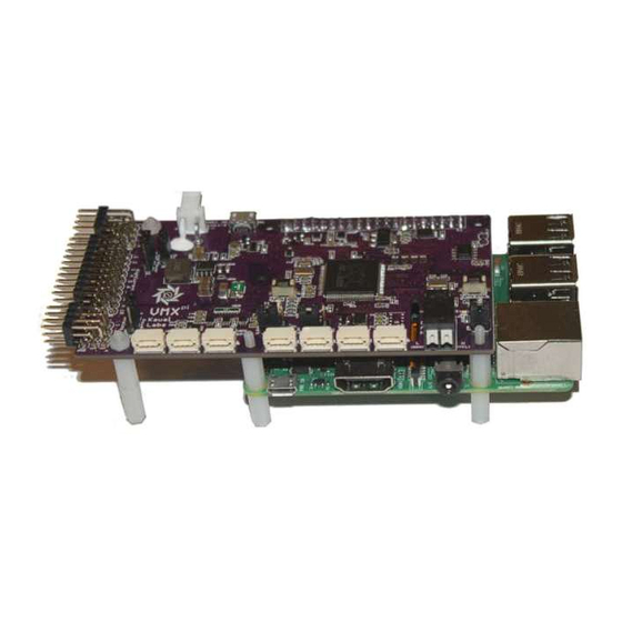
VMX-pi. VMX-pi includes ten (10) Nylon Standoffs and six (6) Nylon Nuts which can be used as shown in the video above to fix the two boards relative to each other and to create a set of stable “legs”... - Page 12 Installation Assembly with Raspberry Pi VMX-pi Standoff Installation – GPIO Connector Side VMX-pi Standoff Installation – HDMI Connector Side The assembly video also demonstrates the installation of the two provided Power Connectors: A Wall-wart (barrel-jack) connector for desktop use and a Battery connector for on-robot use.
- Page 13 Note: as an alternative to using standoffs, an enclosure can be 3D-printed and used instead of the standoffs to create a solid enclosure for protecting and mounting VMX-pi. Raspberry Pi Zero W Raspberry Pi Zero W (top view)
-
Page 14: Roborio Installation
Then, the standoffs included with VMX-pi can be used as shown below to stabilize the two boards relative to each other and to create a set of stable “legs” upon which to mount the assembly onto a Robot. - Page 15 Installation RoboRIO Installation Power VMX-pi [shown in enclosure] powered by 12V battery via Power Distribution Panel (PDP).
- Page 16 As shown in the above picture, the VMX Battery Adapter Cable can connect directly to one of the outputs on the FRC Power Distribution Panel (PDP); the VMX-pi onboard voltage regulator converts the unregulated voltage internally to 5V and 3.3V – and can draw up to a maximum of 3 Amps.
- Page 17 Installation RoboRIO Installation When connected to the same CAN 2.0b bus as the RoboRIO, VMX-pi can be used to monitor the CAN bus traffic between all devices on the CAN bus. When combined with real-time logging, this can enable system-level logging of events in CAN-enabled robots.
-
Page 18: Orientation
RoboRIO Installation Orientation VMX-pi measures a total of 9 sensor axes (3 gyroscope axes, 3 accelerometer axes and 3 magnetometer axes) and fuses them into a 3-D coordinate system. In order to effectively use the values reported by VMX-pi, a few key concepts must be understood in order to correctly install VMX-pi on a robot. - Page 19 Installation Orientation In the diagram above, the green rounded arrows represent Rotational motion, and the remaining arrows represent Linear motion. Axis Orientation Linear motion Rotational Motion Left/Right – Left / + Right + Tilt Backwards X (Pitch) Y (Roll) Forward/Backward + Forward / –...
- Page 20 In order to accomplish this, the yaw (Z) axis must be aligned with the “gravity axis” (the axis that points directly up and down with respect to the earth). When installing VMX-pi on a robot, the VMX-pi yaw (Z) axis and the gravity axis must be aligned.
-
Page 21: Omnimount
VMX-pi is mounted horizontally, vertically, or even upside down. In certain cases, the VMX-pi axes (Board Frame) may not be oriented exactly as that of the Robot (Body Frame). For instance, if the VMX-pi circuit board is mounted sideways, the navX- Micro axes will not be oriented identically to the Robot. - Page 22 Transforming VMX-pi Board Frame to Body Frame with OmniMount VMX-pi’s “OmniMount” feature can transform the VMX-pi X, Y and Z axis sensor data (Board Frame) into Robot Orientation (Body Frame) by detecting which of its three axes is perpendicular to the earth’s surface.
-
Page 23: Creating An Enclosure
OmniMount To configure OmniMount, follow these simple steps: Install VMX-pi onto your robot. ENSURE that one of the VMX-pi axes (as shown on the VMX-pi circuit board) is perpendicular to the earth’s surface. This axis will become the yaw (Z) axis. Note that this axis can either be pointing away from the earth’s surface, or towards the earth’s surface. - Page 24 Installation Creating an Enclosure Design Files The enclosure design files include: File Description Enclosure Bottom 5 Print.STEP Enclosure Base (Solidworks Design File) Enclosure Top 5 Print.STEP Enclosure Base (Solidworks Design File) Enclosure Bottom 5 Print.STL Enclosure Base (STL File for 3D Printing) Enclosure Top 5 Print.STL Enclosure Base (STL File for 3D Printing)
-
Page 25: Software
Raspberry Pi, or remotely across a network. RoboRIO Libraries for accessing VMX-pi IMU data from a National Instruments RoboRIO®-based FRC Robot are now available. To access VMX-pi from a FRC RoboRIO-based system, select the USB interface option available in the navX-MXP RoboRIO libraries. -
Page 26: Windows
VMX-pi Tools for Windows provide several useful tools which help update VMX-pi firmware, configure the real-time motion-processing algorithms, perform advanced calibration of the Magnetometer. These tools are not required to use VMX-pi, but can be useful in certain situations. Kauai Labs recommends all VMX-pi customers install the VMX-pi Tools for Windows. navXUI... - Page 27 Software Windows drivers for communicating over USB with VMX_pi, as well as some additional tools.
-
Page 28: Examples
HAL (C++, Java, C# and Python) The Raspberry Pi HAL examples demonstrate how applications running directly on the VMX-pi host Raspberry Pi – written in a variety of programming languages – can access all VMX-pi functionality for use in Robotics Controller and Robotics Co-processor applications. -
Page 29: Digital Outputs
Examples Digital Inputs Digital Outputs Encoders Interrupts PWM Generation Real-time Clock (RTC) UART... -
Page 30: Vmx-Pi Configuration
UART VMX-pi Configuration RoboRIO (FRC) To access VMX-pi from a FRC RoboRIO-based system, select the USB interface option available in the navX-MXP RoboRIO libraries. Each example includes C++, Java and LabVIEW samples. Note: each example section links to a corresponding page code on the navX-MXP website. -
Page 31: Straight-Line Driving
Examples Rotate to Angle available in the navX-MXP RoboRIO libraries. Straight-line Driving Driving a robot in a straight line using navX-Micro is very similar in nature to the Rotate to Angle example, the only difference being that the robot will move in a direction, and continually adjust the motors, just as in the Rotate to Angle example, to ensure that angular heading is maintained. -
Page 32: Motion Detection
Examples Motion Detection Motion Detection Note: the link below leads to the navX-MXP website. Motion Detection (FRC) Data Monitor Note: the link below leads to the navX-MXP website. Data Monitor (FRC) -
Page 33: Guidance
Best Practices This page summarizes the recommended best practices when integrating VMX-pi with a robot, such as a FIRST FRC robot. Following these best practices will help ensure high reliability and consistent operation. -
Page 34: Terminology
Since VMX-pi measures rotation, errors in the measured angles can occur if VMX-pi is mounted at a point not near the robot center of rotation. For optimal results, VMX-pi should be mounted at the robot’s center of rotation. If VMX-pi cannot be mounted near the robot’s center of rotation, the offset from the center of rotation can be used to correct the yaw angle. - Page 35 VMX-pi is flat, Pitch and Roll angles should be 0. The Yaw angle is different – Yaw is not referenced to anything external. When VMX-pi startup calibration completes, the Yaw angle is automatically set to 0 – thus at this point, 0 degrees represents where the “head”...
- Page 36 Up/Down + Up / – Down Because the gyroscope and accelerometer axes are aligned, VMX-pi measures linear acceleration in the same set of 3 axes used to measure Pitch, Roll and Yaw. However unlike Pitch, Roll and Yaw, acceleration measures linear motion rather than rotation, and is measured in units of G, with a range of +/- 2.0.
- Page 37 Altitude Altitude is a measure of distance in the “up” direction from a reference; VMX-pi (Aero Edition) calculates altitude above sea-level using a pressure sensor. VMX-pi (Aero Edition) altitude has a range of 0 to 25,000 meters.
- Page 38 != 0), VMX-pi performs “tilt correction” fusing the reading from the magnetometers with the pitch and roll angles from the accelerometers. Once corrected, the compass heading is aligned with the VMX-pi Z axis, which ensures that the Yaw angle and the Compass Heading measure rotation similarly.
- Page 39 If you would like to experiment with using the VMX-pi to calculate displacement and velocity, you can use the navXUI’s “Experimental” button to bring up a dialog which displays the...
-
Page 40: Gyro/Accelerometer Calibration
“Body Reference Frame”. This works well as long as the VMX-pi circuit board is in it’s original orientation. However as the VMX-pi circuit board rotates, the X and Y accelerometer axes no longer point “forward/back” and “left/right”... - Page 41 If you are tempted to ignore this information, please read the section entitled “The Importance of Stillness” at the end of this page. Calibration Process The VMX-pi Calibration Process is comprised of three calibration phases: Factory Calibration Startup Calibration On-the-fly Calibration...
- Page 42 Micro. When VMX-pi is re-started, it will perform the Initial Gyro Calibration – the same process that occurs at our factory. NOTE: It is very important to hold VMX-pi still, and parallel to the earth’s surface, during this Initial Gyro Calibration period. You might consider performing this process before using your robot the first time it is used within a new environment (e.g., when...
-
Page 43: Magnetometer Calibration
Guidance Gyro/Accelerometer Calibration NOTE: If VMX-pi is moving during startup, this Yaw Offset Calibration may take much longer than 2 seconds, and may not be calculated at all if the sensor continues moving long enough. Therefore it is highly-recommended to keep VMX-pi still until initial calibration and Initial Yaw Offset calibration completes. - Page 44 Magnetometer Calibration can be accomplished with a single, simple calibration process through the use of the Magnetometer Calibration tool. This tool is designed to run on a Windows computer, and communicate to the VMX-pi circuit board via a USB cable.
-
Page 45: Support
Unpack the contents of the vmx-pi.zip file and run the setup.exe program, which will install the tools as well as all necessary device drivers for communicating over USB with the VMX-pi, as well as some additional tools. In addition, the setup program will install the latest firmware at the following location: <HomeDirectory>\vmx-pi\firmware... -
Page 46: Factory Test Procedure
(X = Major Version Number Y = Minor Version Number Z = Revision Number) 1. Press and hold down the “CAL” button on the VMX-pi circuit board. While holding this button down, connect a USB-micro cable from a Windows PC to the VMX-pi circuit board. - Page 47 Test5 (Normal State): Once the MPU-9250 Selftest and MPU-9250 Calibration are complete, the Orange calibration LED should be OFF, and the S1 and S2 status LEDs should be on. VMX-pi LED States Condition S1 (Green) S2 (Green) 3.3V (Green) Fault (Red)
-
Page 48: Advanced
(e.g., a RoboRio robot controller) via a custom protocol which communicates over USB Serial connection. This protocol defines messages sent between the VMX-pi and the client over the serial USB interface, and includes an error detection capability to ensure corrupted data is not used by the client. - Page 49 Advanced USB Serial Protocol 8-bit Integer (HighNibble)(LowNibble) ‘E9’ 16-bit Integer (HighByte,HighNibble)(HighByt ‘1A0F’ e,LowNibble)(LowByte,HighNib ble)(LowByte,LowNibble) Data Type Encoding (Binary) Binary encoding is used for all Binary message elements. All Binary-formatted data types that are signed are encoded as 2’s complement. All multi-byte data types are in little-endian format.
- Page 50 Message Body Definitions Yaw/Pitch/Roll/Compass Heading Update Message The Yaw/Pitch/Roll/Compass Heading Update message indicates the VMX-pi current orientation and heading, in units of degrees, as follows:...
- Page 51 Note that the accelerometer and gyroscope data has already had bias calibration applied. Additionally, raw magnetometer data is provided. Note that the raw magnetometer data may have already had soft/hard iron calibration applied, if the VMX-pi magnetometer calibration procedure has already been completed. Byte Offset...
- Page 52 Uint8 NAVX_SELFTEST_STATUS Stream Configuration Command By default, VMX-pi begins transmitting YPR Updates upon power up. The Stream Configuration Command is sent in order to change the type of VMX-pi Streaming Update transmitted to the client. Byte Offset Element Data Type...
-
Page 53: Navxui Customization
(NAVX_INTEGRATION_CTL) Parameter Uint32 Integration Control Response The Integration Control Response is sent in response to an Integration Control Command, confiming that certain values being integrated on the VMX-pi have been reset to 0. Byte Offset Element Data Type Action Uint8... -
Page 54: Technical References
VMX-pi and other Inertial Measurement Unit (IMU) and Attitude/Heading Reference System (AHRS) products. Additionally, links to other notable open-source works which could perhaps be adapted to work on the VMX-pi are included. Algorithms...
Need help?
Do you have a question about the VMX-pi and is the answer not in the manual?
Questions and answers