Table of Contents
Advertisement
Advertisement
Table of Contents

Related Manuals for Snap-On SOLUS Ultra


Summary of Contents for Snap-On SOLUS Ultra
- Page 1 User Manual EAZ0075L06D Rev. B 30-A-18 NA...
- Page 2 End User License Agreement. The Snap-on Incorporated Software End User License Agreement may be provided with the diagnostic tool, and is available at: https://eula.snapon.com/diagnostics. Patent Information For a listing of Snap-on products that are protected by patents in the United States and elsewhere, visit: https://patents.snapon.com User Manual Information This manual includes information and images applicable with diagnostic software version 18.4 and later.
- Page 3 - Click on the “Training & Support” tab, select the applicable diagnostic tool, then select “See Training”. NOTE: Sample titles are listed below. Not all titles may be available for all diagnostic tools, and are subject to change. Snap-on® Training Solutions® - Training Videos (examples) Introduction and Navigation Global OBD-II Scanner Codes...
- Page 4 Diagnostic Quick Tips - Video Series Snap-on Diagnostic Quick Tips videos are available at no charge on our website and on our YouTube channel. These videos are developed from real repair case studies to help professional technicians use diagnostic tools to solve specific vehicle problems (e.g.
- Page 5 Diagnostic Quick Tips - Video Series Snap-on® Training Solutions® - Diagnostic Quick Tips Videos (examples) Hyundai Blind Spot Detection System Chrysler HVAC Test Calibration Chrysler VVT System Cleaning Hyundai Occupant Detection System Reset Chrysler Wheel & Tire Calibrations Ignition Coil Current and Voltage Comparison...
-
Page 6: Table Of Contents
Contents Chapter 1: Using This Manual ....................5 Content ............................5 Conventions..........................5 Terminology ........................... 5 Symbols ..........................5 Bold Text ..........................6 Notes and Important Messages ..................... 6 Hyperlinks ..........................6 Procedures..........................6 Chapter 2: Introduction......................7 Control Buttons..........................7 Data and Power Connections....................... - Page 7 Contents Exiting Scanner .......................... 41 Chapter 5: OBD-II/EOBD ......................42 Basic Operations ........................42 Screen Layout and Toolbar Controls ................... 42 Connecting the Data Cable ....................42 Saving and Reviewing Data Files ..................42 OBD-II/EOBD Menu ........................42 OBD Health Check....................... 43 OBD Direct ...........................
- Page 8 Safety Information READ ALL INSTRUCTIONS For your own safety, the safety of others, and to prevent damage to the product and vehicles upon which it is used, it is important that all instructions and safety messages in this manual and the accompanying Important Safety Instructions manual be read and understood by all persons operating, or coming into contact with the product, before operating.
- Page 9 Safety Information Safety Signal Words Safety Signal Words All safety messages contain a safety signal word that indicates the level of the hazard. An icon, when present, gives a graphical description of the hazard. Safety Signal words are. Indicates an imminently hazardous situation which, if not avoided, will result in death or serious injury to the operator or to bystanders.
-
Page 10: Chapter 1 Using This Manual
Using This Manual Chapter 1 1.1 Content This manual contains basic operating instructions and is structured in a manner to help you become familiar with your Diagnostic Tool features and perform basic operations. The illustrations in this manual are intended as reference only and may not depict actual screen results, information, functions or standard equipment. -
Page 11: Bold Text
Using This Manual Conventions 1.2.3 Bold Text Bold emphasis is used in procedures to highlight selectable items such as control buttons, icons and menu options. Example: Press the OK button 1.2.4 Notes and Important Messages The following messages are used. Notes A NOTE provides helpful information such as additional explanations, tips, and comments. -
Page 12: Chapter 2: Introduction
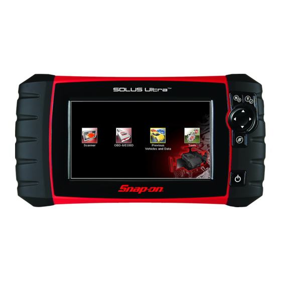
Introduction Chapter 2 ® The SOLUS Ultra Diagnostic Tool interfaces with the electronic control system of a vehicle to retrieve diagnostic trouble codes (DTCs), access serial data stream information, and command bi-directional tests. Various vehicle control systems, such as engine, transmission, and antilock brake system (ABS), are readily diagnosed using this Diagnostic Tool. -
Page 13: Data And Power Connections
Introduction Data and Power Connections Item Button Description Buttons move the cursor or highlight in their respective direction: Up ( Directional - Thumb • pad rocker type buttons Down ( • Left ( • Right ( • Programmable function button that can provide a S (Shortcut) - Push type shortcut for performing a variety of routine tasks. -
Page 14: Battery Pack And Stand
Introduction Battery Pack and Stand 2.3 Battery Pack and Stand Figure 2-3 Rear view Item Description Built in-Stand (shown closed) - The built-in stand extends from the back of the Diagnostic Tool and clips into the Diagnostic Tool for storage. Battery Cover 2.4 Power Sources Your Diagnostic Tool can receive power from any of the following sources:... -
Page 15: Internal Battery Pack
Introduction Power Sources 2.4.1 Internal Battery Pack The Diagnostic Tool can be powered from the internal rechargeable battery pack. A fully charged battery provides sufficient power for about 3 hours of continuous operation. Battery charging occurs when the Diagnostic Tool is connected to the AC Power Supply and to a live AC power source. -
Page 16: Technical Specifications
Introduction Technical Specifications 2.5 Technical Specifications Item Description / Specification Touch Screen Resistive Touch Panel 7.0 inch diagonal, Color LCD Display 800 x 480 resolution SWVGA Rechargeable lithium-ion battery pack Battery Approximately 2 hour run time Approximately 5 hour charge time Power Supply Supply Rating;... -
Page 17: Chapter 3 Basic Operation And Navigation
Basic Operation and Chapter 3 Navigation This chapter describes basic Diagnostic Tool operation, navigation, screen layout, icon functions, and screen messages. Before you operate the Diagnostic Tool, make sure the battery pack is fully charged or the Diagnostic Tool is powered by the AC power supply. 3.1 Turning On/Off and Emergency Shutdown The following sections describe how to turn the Diagnostic Tool on and off and how to perform an emergency shutdown. -
Page 18: Emergency Shutdown
Basic Operation and Navigation Basic Navigation 3.1.3 Emergency Shutdown IMPORTANT: Using the emergency shutdown procedure while communicating with the vehicle ECM may lead to ECM problems on some vehicles. During normal operation turn the Diagnostic Tool off using the Turning Off procedure above. The emergency shutdown procedure should only be used If the Diagnostic Tool does not respond to navigation or control buttons or exhibits erratic operation. -
Page 19: Title Bar
Basic Operation and Navigation Basic Navigation 3.2.2 Title Bar The title bar at the top of the screen provides basic information about current Diagnostic Tool operating conditions. Title bar options vary depending upon vehicle make and model, what function is active, what test is being performed, or what menu is selected. The title bar contains information only, there are no selectable items. -
Page 20: Home Screen Icons
Basic Operation and Navigation Basic Navigation 3.2.3 Home Screen Icons Each available Diagnostic Tool function is represented by a icon on the home screen. The table below provides descriptions of the icon functions. Select an icon from the Home screen to start a function. You can also use the control buttons to activate a function, a yellow border around the icon indicates it is highlighted, or in focus. -
Page 21: Common Toolbar Control Icons
Basic Operation and Navigation Basic Navigation 3.2.4 Common Toolbar Control Icons Common control icon functions are described in the following table. Specific function control icons are described in their applicable chapters. Displayed control icons vary depending on the active function or test. Select a control icon on a screen to activate a control function. You can also use the control buttons to activate a function, a yellow border around the icon indicates it is highlighted, or in focus. -
Page 22: Scroll Bar
Basic Operation and Navigation Basic Navigation 3.2.5 Scroll Bar A vertical scroll bar appears along the right-hand edge of the screen when additional data expands above or below what is currently on the screen (Figure 3-2). Figure 3-2 Scroll bar Beginning - Moves to beginning of data displayed 2—... -
Page 23: Screen Messages
Basic Operation and Navigation Screen Messages 3.3 Screen Messages 3.3.1 System Messages There are four types of system messages that may be displayed: Message Type Description Loading and connecting messages display when the Diagnostic Tool is performing an Loading and internal operation, such as loading a database, establishing communications with the Connecting vehicle, or initiating a test. -
Page 24: Data Cable Connection
Basic Operation and Navigation Data Cable Connection 3.4 Data Cable Connection Connection of the data cable to the Diagnostic Tool and vehicle DLC is required for Scanner and OBD-II/EOBD testing. Depending on the vehicle, the supplied DA-4 data cable may be used alone or may require optional adapters. -
Page 25: Chapter 4 Scanner
Scanner Chapter 4 This chapter describes the basic operation of the Scanner function. The Scanner icon is located on the Home screen. The Scanner function allows your Diagnostic Tool to communicate with the electronic control systems of a vehicle. This allows you to retrieve diagnostic trouble codes (DTCs), view PID data and perform diagnostic tests. -
Page 26: Scanner Control Icons
Scanner Scanner Demonstration Program 4.1.2 Scanner Control Icons The scanner toolbar contains control icons. Control icons may vary depending on the active function or test. A yellow frame surrounding an icon (highlighted), indicates it is selected. Other control icons (not shown) are described in Common Toolbar Control Icons, on page 16. -
Page 27: Scanner Operation
Scanner Scanner Operation 4.3 Scanner Operation Starting Scanner opens a menu list of vehicle manufacturers and begins the process by identifying the vehicle being tested. After the vehicle is identified, a vehicle system is selected and then a specific test or function is selected to allow you to retrieve diagnostic trouble codes (DTCs), view and save PID data, or perform diagnostic tests. -
Page 28: Connecting The Data Cable
Scanner Scanner Operation The list includes Demonstration, which opens the Demonstration program (see Scanner Demonstration Program, on page 21). 2. Select the vehicle manufacturer from the list. A model year menu displays. 3. Select the vehicle year from the menu. A list of vehicle types or models displays. -
Page 29: System And Test Selection
Scanner Scanner Operation 4.3.3 System and Test Selection After a vehicle is selected, a menu of available systems is displayed. Select a system to continue. Figure 4-4 Available systems list NOTE: Only the systems available for testing on the identified vehicle are included in the list. After a system is selected and the Diagnostic Tool establishes communication with the vehicle, a menu, of available tests is displayed. - Page 30 Scanner Scanner Operation Main menu options vary slightly by the year, make, and model of the test vehicle. The main menu may include: Codes Menu—displays diagnostic trouble code (DTC) records from the vehicle electronic • control module. Selecting may open a submenu of viewing options. Clear Codes—erases DTC records and other data from the ECM.
- Page 31 Scanner Scanner Operation Codes Menu This selection may appear as Codes, Codes Menu, Codes Only, Codes (No Data), Service Codes or something similar on the menu. Selecting opens a list of viewing options that includes: Display Codes • Clear Codes, on page 31 •...
- Page 32 Scanner Scanner Operation Figure 4-7 Typical - DTC (.XML) files in the View Saved Data list Saved (.XML) files can also be transfered to a personal computer (PC) using ShopStream Connect. Once the Diagnostic Tool is connected to the PC, (.XML) files can be printed, transferred, and copied.
- Page 33 Scanner Scanner Operation Code Scan One of the benefits of performing a code scan is that you can quickly show your customer diagnostic related issues with a pre scan report, and then after repairing the issues you can use the post scan report to show that the repairs were completed (Figure 4-9).
- Page 34 Scanner Scanner Operation Depending on the vehicle, Code Scan (if supported) may be available from the Systems menu. Selecting Code Scan starts an active scan of vehicle control modules, and opens the Code Scan results screen (Figure 4-10). A progress indicator is shown at the top indicating the active scanning progress.
- Page 35 Scanner Scanner Operation Figure 4-11 System icon (opens Main Menu) Saving Codes, and Code Scan Results) When using the code scan feature, or when viewing individual system codes (e.g. engine, transmission) selecting the Save icon from the toolbar saves the results as a data file. The saved file(s) can be viewed using two methods: On the diagnostic tool - See View Saved...
- Page 36 Scanner Scanner Operation Clear Codes The Diagnostic Tool clears codes from the vehicle electronic control module memory on most vehicles. If this function is not available on the test vehicle, Clear Codes does not appear as a menu option. NOTE: Clear Codes is also available from OBD-II Health Check (see OBD Health Check, on page 43).
- Page 37 Scanner Scanner Operation The toolbar control icons are described in Scanner Control Icons, on page 21 and Common Toolbar Control Icons, on page 16. During data display the main body of the screen is divided into two columns; the left-hand column has a description of the parameter and the right-hand column shows the parameter value or state.
- Page 38 Scanner Scanner Operation b. Selecting the Select/Deselect icon activates it. Now you can add or remove parameters by selecting individual entries in the list. Note the following: Items at the top of the list that cannot be highlighted are locked and cannot be turned off. –...
- Page 39 Scanner Scanner Operation Locking Parameters Use the Lock/Unlock icon to hold selected lines of the data in place and prevent them from scrolling, or to release previously locked lines of data. Up to three lines of data may be held at a time.
- Page 40 Scanner Scanner Operation Setting Trigger Levels The trigger icon allows you to configure the Diagnostic Tool to automatically save PID data from buffer memory to a file when a parameter value crosses a threshold. When triggering is armed, a "Trigger event" pauses data collection and saves data to a file. Selecting the Trigger icon opens a menu that includes: Set Trigger—establishes upper and lower signal values to initiate an event capture for the •...
- Page 41 Scanner Scanner Operation 5. Select a on the toolbar, or press the Y/a button, to set the upper threshold. A lower trigger level line now appears at the mid-point of the graph. 6. Select the plus (+) and minus (–) icons on the toolbar, or use the up b and down d arrow buttons to position the lower trigger level line to where you want it on the graph.
- Page 42 Scanner Scanner Operation The toolbar control icons are described in Scanner Control Icons, on page 21 and Common Toolbar Control Icons, on page 16. To save data: Select Save. • A save dialog box displays while data is being saved. The data is saved when the message box disappears.
- Page 43 Scanner Scanner Operation Use the slider to quickly scroll through the data. Use the control icons to accurately position the cursor. The cursor (vertical line), indicates your position when in the graph mode, appears once you begin navigating (Figure 4-17). 1—...
- Page 44 Scanner Scanner Operation Functional Tests The Functional Tests selection is used to access vehicle-specific subsystem tests. Available tests vary by manufacturer, year, and model. Only the tests available for the identified vehicle display in the menu. There are several types of functional tests: Information Tests—these are read-only tests, like selecting “VIN”...
- Page 45 Scanner Scanner Operation Generic Functions Generic Functions are use to perform generic OBD-II/EOBD tests, for additional information see OBD-II/EOBD, on page 42. Troubleshooter ® Fast-Track Troubleshooter is a database of experience-based repair strategies and information, that has been compiled and validated by top-notch technicians. Troubleshooter simplifies the diagnosis process, as it contains information on virtually all common diagnostic trouble code (DTC) problems and driveability symptoms.
-
Page 46: Exiting Scanner
Scanner Exiting Scanner Certain PID data parameter values display directly within the tip when performing Troubleshooter tests and procedures. A tip may also contain a hyperlink to a Troubleshooter Reference, another test or procedure, or a supplemental operation, such as Clear Codes. Hyperlinks are shown in blue, and selecting them opens the link. -
Page 47: Chapter 5: Obd-Ii/Eobd
OBD-II/EOBD Chapter 5 This chapter describes the basic operation of the OBD-II/EOBD function. The OBD-II/EOBD icon is located on the Home screen. The OBD-II/EOBD function allows you to access “generic” OBD-II/EOBD data. Generic OBD-II/EOBD data is data limited to emission related diagnostics such as: Checking for emissions-related diagnostic trouble codes (DTCs) •... -
Page 48: Obd Health Check
OBD-II/EOBD OBD-II/EOBD Menu 5.2.1 OBD Health Check The OBD-II Health Check offers a way to quickly check for and clear generic DTCs, and to check readiness monitors for emissions testing. Selecting opens a connection message, then a submenu of test options (Figure 5-1). - Page 49 OBD-II/EOBD OBD-II/EOBD Menu Codes The Codes option displays a list of current emission related DTCs. OBD-II/EOBD Codes have a priority according to their emission severity, with higher priority codes overwriting lower priority codes. The priority of the code determines the illumination of the MIL and the code erase procedure.
-
Page 50: Obd Direct
OBD-II/EOBD OBD-II/EOBD Menu Figure 5-3 Readiness monitor test report Scroll to view the entire list of Readiness Monitors to ensure that all tests are complete. It is possible to save the monitor report as part of the vehicle records. Select Save from the toolbar and follow the screen prompts. - Page 51 OBD-II/EOBD OBD-II/EOBD Menu To perform an OBD-II/EOBD Test: 1. Select Start Communications from the OBD-II/EOBD menu. A vehicle type options list displays: 12V Light Duty Vehicle – 24V Heavy Duty/Goods Vehicle – 2. Select an option from the vehicle type list. A connection message displays.
- Page 52 OBD-II/EOBD OBD-II/EOBD Menu IMPORTANT: All service modes are not supported by all vehicles, so the available menu selections will vary. 6. Select a test to continue. Readiness Monitors Use this menu item to check the readiness of the monitoring system. If a monitor system is not supported, it is not displayed.
- Page 53 OBD-II/EOBD OBD-II/EOBD Menu ($02) Display Freeze Frame Data Freeze frame data provides a “snapshot” of critical parameter values at the time a DTC set. This item is used to display freeze fame data for any stored emission related diagnostic trouble code (DTC).
- Page 54 OBD-II/EOBD OBD-II/EOBD Menu ($05, 06, 07) Display Test param./Results This option opens a submenu of parameters and test results form various sensors, monitor test results, and a record of DTC setting conditions detected during the last drive cycle. The submenu includes: ($05) Oxygen Sensor Monitoring •...
- Page 55 OBD-II/EOBD OBD-II/EOBD Menu Figure 5-7 Performance tracking display ($0A) Emission Related DTC with Permanent Status This option displays a record of any “permanent” codes. A permanent status DTC is one that was severe enough to illuminate the MIL at some point, but the MIL may not be on at the present time. Whether the MIL was switched off by clearing codes or because the setting conditions did not repeat after a specified number of drive cycles, a record of the DTC is retained by the ECM.
- Page 56 OBD-II/EOBD OBD-II/EOBD Menu Manual Protocol Selection Communication protocol is a standardized way of transferring data between an ECM and a Diagnostic Tool. Global OBD may use the following communication protocols: ISO 15765-4 (CAN) • ISO 27145 (WWHOBD CAN) • ISO J1939 (CAN) •...
-
Page 57: Chapter 6 Previous Vehicles And Data
Previous Vehicles and Data Chapter 6 This chapter describes the basic operation of the Previous Vehicles and Data function. The Previous Vehicles and Data icon is located on the Home screen. This function allows you to select recently tested vehicles and access saved data files. 6.1 Previous Vehicles and Data Menu The following options are available from the Previous Vehicles and Data menu: Vehicle History... -
Page 58: View Saved Data
Previous Vehicles and Data Previous Vehicles and Data Menu To select from the vehicle History: 1. Select Previous Vehicles and Data from the Home screen. 2. Select Vehicle History from the menu. A list of up to 25 previously tested vehicles displays. Each vehicle is given a unique file name that includes the vehicle ID, date, and time. - Page 59 Previous Vehicles and Data Previous Vehicles and Data Menu To review a movie: 1. Select Previous Vehicles and Data from the Home screen. 2. Select View Saved Data from the menu. 3. Select a movie from the list of saved files. The movie opens and plays in real time.
-
Page 60: Delete Saved Data
Previous Vehicles and Data Previous Vehicles and Data Menu Viewing Code Results on the Diagnostic Tool Selecting a system code or a code scan results file from your saved file list (Figure 6-4), opens the file onscreen. When opened, the (.XML) file displays basic vehicle information and a list of DTCs with a brief description of each. -
Page 61: Chapter 7 Tools
Tools Chapter 7 This chapter describes the basic operation of the Tools function. The Tools icon is located on the Home screen. This function allows you to configure Diagnostic Tool settings to your preferences. 7.1 Tools Menu The following options are available from the Tools menu: Connect to PC—use to transfer and share files with a personal computer (PC) •... -
Page 62: Connect To Pc
Tools Tools Menu 7.1.1 Connect to PC Connect-to-PC allows you to transfer saved data files on your diagnostic tool to your personal computer using a USB cable. The optional ShopStream Connect™ PC software allows you to view, print and save data files on your PC. -
Page 63: System Information
Tools Tools Menu Toggle Record/Pause—programs the Shortcut button to work as the Pause and Record • buttons. The first press pauses data collection and the second press resumes live data. To assign a function to the Shortcut button: 1. Select Tools from the Home screen. The Tools menu opens. - Page 64 Tools Tools Menu System Settings Selecting System Settings opens a menu with two options; Display and Date & Time. Either selection opens an additional menu. Display options include: Brightness‚ on page 59—adjusts the intensity of the screen back lighting. • Color Theme‚...
- Page 65 Tools Tools Menu Color Theme This option allows you to select between a white and black background for the screen. The black background can be beneficial when working under poor lighting conditions. Selecting opens a menu with two choices: Day Theme (white background) and Night Theme (black background).
- Page 66 Tools Tools Menu Selecting opens a menu with two choices; Color Toolbar and High Contrast Toolbar. Select and a “please wait” message displays followed by the Home screen. The new setting is now active. Font Type This option allows you to select between standard and bold faced type for the display screen. Bold type makes screen writing more legible under poor lighting or bright sunlight conditions.
- Page 67 Tools Tools Menu Figure 7-7 Calibration screen 4. Touch each box on the screen as it displays. The display returns to the Settings menu once the screen calibration procedure is complete. IMPORTANT: It is critical to complete the touch screen calibration sequence once it has begun. Never power down the unit while a screen calibration is in process, serious damage to the unit may result.
- Page 68 Tools Tools Menu Figure 7-8 Clock Settings screen 4. Tap the up (+) icon on the screen or press the up (b) button on the keypad to incrementally increase the number in the highlighted field. Tap the down (–) icon on the screen or press down (d) on the keypad to incrementally decrease the number.
- Page 69 Tools Tools Menu Date Format This option allows you to select how date information is displayed. Select from: (MM_DD_YYYY)—Month, Day, Year • (DD_MM_YYYY)—Day, Month, Year • (YYYY_MM_DD)—Year, Month, Day • Make a selection, then tap the Back icon or press the N/X button to return to the menu. Configure Scanner This option determines whether or not the scales are displayed on the data graphs when using the Scanner.
- Page 70 Tools Tools Menu Configure Units Selecting opens a dialog box that allows you to choose between US customary or metric units of measure for temperature, vehicle speed, air pressure, and other pressures. Figure 7-10 Configure Units menu To change the units setup: 1.
-
Page 71: Chapter 8 Maintenance
Maintenance Chapter 8 This chapter covers how to care for your Diagnostic Tool. 8.1 Cleaning and Inspecting the Diagnostic Tool When using the Diagnostic Tool perform the following tasks to keep it in top shape: Check the housing, wiring, and connectors for dirt and damage before and after each use. •... -
Page 72: Battery Safety Guidelines
If the battery pack no longer holds a charge, contact your sales representative to order a new one. IMPORTANT: Replace the battery pack with original Snap-on replacement parts only. To replace the battery pack: 1. Loosen the two captive screws that secure the battery pack to the back of the unit. -
Page 73: Disposing Of The Batteries
Maintenance Battery Service 1— Battery Cover 2— Captive Screws Figure 8-1 Battery pack replacement 8.2.3 Disposing of the Batteries Always dispose of a lithium-ion battery pack according to local regulations, which vary for different countries and regions. The battery pack, while non-hazardous waste, does contain recyclable materials. -
Page 74: Chapter 9: Shopstream Connect
ShopStream Connect Chapter 9 This chapter includes a brief introduction to some of the key features of the ShopStream Connect software. For detailed ShopStream Connect information and instructions, download the ShopStream Connect User Manual from our website: http://diagnostics.snapon.com/usermanuals The ShopStream Connect™ (SSC) software is PC-based software that extends the capabilities of your diagnostic tool. -
Page 75: Ssc Main Screen
ShopStream Connect SSC Main Screen If the ShopStream Connect software does not open, open it from the Windows Start menu or use the ShopStream Connect shortcut icon on the Windows desktop (automatically created during installation). 9.2 SSC Main Screen The ShopStream Connect software will open automatically when you connect the diagnostic tool to your PC USB connection, Using SSC (Connecting to your PC)‚... -
Page 76: Scanner Dataviewer
ShopStream Connect Scanner DataViewer 6— Main display—shows stored data files details. NOTE: The files listed are sortable (ascending/descending) by clicking on the column tab at the top (e.g. File Name, Type, etc.) Sort preferences are saved when the ShopStream Connect program is closed. 7—... -
Page 77: Image Viewer
ShopStream Connect Image Viewer 9.4 Image Viewer SSC allows you to view and print .bmp, .jpg and .sps image files (screenshots) saved on your diagnostic tool, with your PC. NOTE: File extension types vary depending on the diagnostic tool. Not all the file extensions described here may be available on your diagnostic tool. -
Page 78: Printing The Code Scan Report
ShopStream Connect Printing the Code Scan Report 9.5 Printing the Code Scan Report To print the Code Scan Report, the saved code scan .XML file must be opened using ShopStream Connect. To print the Code Scan Report using ShopStream Connect: 1. - Page 79 ShopStream Connect Printing the Code Scan Report Selecting Print opens the Windows print dialog window (Figure 9-7). Select your printer from the list, then select Print to print the report. My printer 1 My printer 2 Figure 9-7...
-
Page 80: Software Upgrades And Updates
1. Select Tools > Update Software > (diagnostic tool type - e.g. ETHOS Edge, MODIS Edge, SOLUS Edge, etc.) from the Menu bar (Figure 9-8). The software checks the Snap-on web server for available updates. My Diagnostic Tool Figure 9-8 2. If service release updates are available, select Next to continue, then select Download and... -
Page 81: End User License Agreement
Use of Software is governed by the terms and conditions of the End User License Agreement. The diagnostic tool should not be initially operated until the End User License Agreement is read. Use of the device acknowledges your acceptance of the End User License Agreement. The Snap-on Incorporated Software End User License Agreement is available at: https://eula.snapon.com/... -
Page 82: Chapter 10 Suretrack Community
SureTrack Community Chapter 10 10.1 SureTrack - Online Community Your diagnostic tool includes access to the online SureTrack Community. You can use your PC to access the latest Real Fixes, Related Tips, and Common Repair Procedures information. SureTrack is an evolving database of "real-world" automotive repair knowledge based on expert knowledge and millions of actual repair orders. -
Page 83: Finding Your Suretrack Authorization Code
SureTrack - Online Community 10.1.3 Finding your SureTrack Authorization Code When you purchase a qualifying upgrade/plan, or platform from your Snap-on Representative, you will receive a SureTrack authorization code. The authorization code is printed on your sales receipt. Authorization codes are 12 digit alpha-numeric codes (e.g. 123ABCAP4-US). -
Page 84: Creating A Suretrack Account
SureTrack Community SureTrack - Online Community 10.1.4 Creating a SureTrack Account Use Requirements To use SureTrack you must: Create a SureTrack Account, see Creating an Account‚ on page 79. • Have a current SureTrack Authorization Code, see Finding your SureTrack Authorization •... - Page 85 SureTrack Community SureTrack - Online Community Enter all required information. Email Address* First Name* Last Name* Phone Number Address Line 2 City* State* Zipcode Username* Password* Retype Password* Cancel Create Figure 10-4 Success Congradulations! Your account has been created. This account can be used to contribute to the community and manage your profile.
- Page 86 SureTrack Community SureTrack - Online Community Choose 3 security questions. Select three security questions below. These questions will help us verify your identity should you forget your password. Question 1: Choose a question... Question 2: Choose a question... Question 3: Choose a question...
- Page 87 SureTrack Community SureTrack - Online Community Enter all required Enter the SureTrack information Authorization Code (scroll down) Technician Profile Manager User Profile Activation Mode Expert Subscriptions Authorization Key Account Expiration Date Communication Personal Profile Cancel First Name Rank: New Member Click “Save”...
-
Page 88: Logging In (Active Account)
SureTrack Community SureTrack - Online Community 10.1.5 Logging In (active account) If you have previously created a SureTrack account, and have a valid username and password, select LOGIN (Figure 10-11) from the ShopKey Pro start page, and then complete the login process (Figure 10-12). -
Page 89: Logging In With New Authorization Code (Active Account)
SureTrack Community SureTrack - Online Community 10.1.6 Logging In with New Authorization Code (active account) Use the following instructions, if you have purchased a qualifying upgrade/plan and your SureTrack account is active (has not expired). To find your new authorization code, see Finding your SureTrack Authorization Code‚... -
Page 90: Logging In With New Authorization Code (Expired Account)
SureTrack Community SureTrack - Online Community 7. Exit the Profile Manager by selecting your username (near the top right) and select Logout. 8. When the login screen displays, login using your current username and password. 9. Confirm the new expiration date by logging back into Profile Manger to check it. 10.1.7 Logging In with New Authorization Code (expired account) Use the following instructions, if your SureTrack account has expired, and you have purchased a... - Page 91 SureTrack Community SureTrack - Online Community Figure 10-16 4. Scroll to the topic “Where do I apply my new Authorization Key from Snap-on?” 5. Select the link “click here to log into the profile manager login window directly”. URL - https://profilemanager.mitchell1.com/technicianprofile/index –...
-
Page 92: Suretrack Features
SureTrack Community SureTrack - Online Community 10.1.8 SureTrack Features SureTrack is an integrated part of ShopKey Pro, and includes two navigation modules providing search and forum capabilities: 1Search™ Limited • Sure Track Community. • 1Search™ Limited The 1Search Limited module includes the following information features: Real Fixes and Tips - real-world fixes and repair tips captured from actual repair orders and •... -
Page 93: Suretrack Screens
SureTrack Community SureTrack - Online Community 10.1.9 SureTrack Screens SureTrack Home Page (within ShopKey Pro) The SureTrack Home page within ShopKey Pro includes: Username Figure 10-18 1. Change Vehicle* - dropdown menu provides options to change the active vehicle 2. Active Vehicle* - displays active vehicle 3. - Page 94 SureTrack Community SureTrack - Online Community 1Search Limited Top 10 Results Page Selecting 1Search Limited displays a Top 10 results page which includes: Figure 10-19 Search Bar - use the search bar to enter a code, component or symptom to search. For best •...
- Page 95 SureTrack Community SureTrack - Online Community Results Index Page The Results Index page includes: OEM Plus Results - provides results that best match the exact search criteria, ranked in • order with the closest match at the top. SureTrack Results - provides probable components related to the search criteria, ranked in •...
- Page 96 SureTrack Community SureTrack - Online Community SureTrack Results Page Selecting an item from the Results Index page displays applicable repair information on the SureTrack results page. Figure 10-21 Information may include: Real Fixes and Tips - real-world fixes and repair tips captured from actual repair orders and •...
- Page 97 SureTrack Community SureTrack - Online Community ProView Results Page Selecting the ProView tab from the SureTrack results page opens ProView. ProView provides graphical displays showing the direct relationship between a code or symptom to the component used to fix them. Figure 10-22 Information may include: Radial Graph - showing the relationship of the code or symptom to possible at fault...
Need help?
Do you have a question about the SOLUS Ultra and is the answer not in the manual?
Questions and answers