Table of Contents
Advertisement
Use, features
Use
Features
CC1N7101en
29.06.2006
Gas Burner Controls
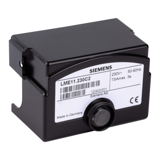
Gas burner controls for the supervision of 1- or 2-stage gas burners of small to
medium capacity (typically up to 350 kW), in intermittent operation.
The LME... and this Data Sheet are intended for use by OEMs which integrate the
burner controls in their products.
LME... burner controls are used for the startup and supervision of 1- or 2-stage gas
burners in intermittent operation. The flame is supervised by an ionization probe or
flame detector QRA... with ancillary unit AGQ3... or blue–burning flames with blue-
flame detectors QRC...
In terms of housing dimensions, the LME... are identical with the LGB... and LMG...
burner controls (refer to «Type summary»).
Burner controls conforming to EN 298
-
For gas burners with fans conforming to EN 676
-
Undervoltage detection
-
Air pressure supervision with functional check of the air pressure switch during
-
startup and operation
Electrical remote reset facility
-
Multicolor indication of fault status and operational status messages
-
Limitation of the number of repetitions
-
Accurate control sequence thanks to digital signal handling
-
Controlled intermittent operation after 24 hours of continuous operation
-
7
101
LME...
Building Technologies
HVAC Products
Advertisement
Table of Contents

Summarization of Contents
Gas Burner Controls LME Series
Use and Features Overview
Overview of the burner controls' application and key characteristics.
Safety and Engineering Notes
Warning Notes for Safe Operation
Essential safety precautions to avoid injury and damage during operation.
Engineering and Mounting Guidelines
Technical considerations for integration and compliant installation.
Installation and Connection Details
Installation Notes and Wiring
Best practices for cable routing, connections, and local regulations.
Flame Detector Electrical Connection
Requirements for reliable signal transmission from flame detectors.
Commissioning, Standards, and Disposal
Commissioning and Safety Checks
Safety checks required during initial setup and maintenance procedures.
Standards, Certificates, and Service
Compliance with directives, certifications, service adapter use, and disposal.
Product Design and Diagnostics
Mechanical Design and Components
Description of the plug-in design, housing, and internal components.
Indication, Diagnostics, and Versions
Status LEDs, diagnostic interface, and model-specific features.
Type Summary
Burner Control Type References and Timings
Table detailing type references, applications, and timing parameters.
Ordering Information and Accessories
Controls, Connections, and Detectors
Information on ordering burner controls, accessories, and flame detectors.
Actuators, Ancillary Units, and Tools
Details on actuators, UV supervision units, RC units, and service adapters.
Technical Data - General and Environmental
General Unit Specifications
Electrical specs, weight, safety class, protection degree, and current ratings.
Environmental Operating Conditions
Storage, transport, and operation conditions including temperature and humidity ranges.
Technical Data - Flame Supervision
Ionization Probe Flame Supervision
Specifications for ionization probes, including voltage, thresholds, and current.
Technical Data - UV Flame Supervision
UV Detector and Ancillary Unit Data
Specifications for UV detectors (QRA) and AGQ3 ancillary units.
Technical Data - QRC Flame Supervision
QRC Flame Detector Data
Detector current requirements and status indication for QRC flame detectors.
Green LED Status Interpretation
Meaning of the green LED for operational status and flame signal stability.
Burner Control Functions and Fault Handling
Startup Preconditions and Operation
Conditions for startup, undervoltage behavior, and intermittent operation.
Fault Sequence, Reset, and Repetitions
Fault responses, lockout procedures, resetting, and repetition limits.
Operation, Indication, and Diagnostics
Operation and Reset Button Functionality
Role of the reset button for operation, diagnostics, and status indication.
Visual Status Indication via LED
Color code table for the multicolor signal lamp indicating operational states.
Diagnostics of Fault Causes
Activating and Interpreting Error Codes
Sequence to activate diagnostics and interpret fault causes using LED blink patterns.
Control Sequence - LME11
Connection Diagram and Timing Sequence
Wiring diagram and timing chart for the LME11 burner control.
Control Sequence - LME21
Connection Diagram and Timing Sequence
Wiring diagram and timing chart for the LME21 burner control.
Application Examples for LME11/21/22
Wiring examples for LME11, LME21, and LME22 with different burner configurations.
Application Examples - LME21 Actuator Control
2-Stage Modulating Burner Actuator Control
Examples of controlling 2-stage actuators with LME21, including SQN models.
Control Sequence - LME22/LME23
Connection Diagram and Timing Sequence
Wiring diagram and timing chart for LME22 and LME23 burner controls.
Application Examples - LME22 Actuator Control
2-Stage Modulating Burner Actuator Control
Examples of 2-stage modulating burner control with SQN actuators.
Control Sequence - LME44
Connection Diagram and Timing Sequence
Wiring diagram and timing chart for the LME44 burner control.
Legend and Terminology
Component and Parameter Definitions
Definitions for abbreviations, components, and timing parameters used in the manual.
Product Dimensions
LME Burner Control Dimensions
Physical dimensions of the LME burner control unit in millimeters.
Ancillary Unit AGQ3 Dimensions
Physical dimensions of the AGQ3 ancillary unit and available types.


Need help?
Do you have a question about the LME44 series and is the answer not in the manual?
Questions and answers