Advertisement
FM739
Use
CC1N7761E
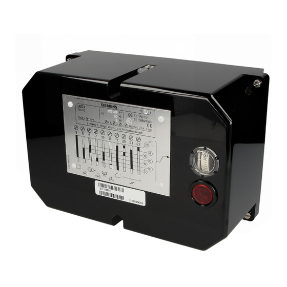
Control Unit
Control unit for double or multi-flame supervision of oil, gas or forced draught
oil/gas burners of any fuel throughput (for continuous or intermittent operation).
The LEC1... control unit is designed for the fully automatic start-up and supervision of
those forced draught burners with which the flame supervision should or must be carried
out by separate flame safeguards, e.g. with
-
Dual supervision (of the main flame or of the pilot and main flame by means of two
identical or different detectors).
-
Supervision of forced draught oil/gas burners (with different types of detectors
according to selected operating mode).
-
Multi-flame supervision (i.e. central and simultaneous control of the start-up and
supervision program for several burners, the flames of which, however, must be
individually supervised by one or two flame safeguards each).
The following flame safeguards are available:
LAE10... for the supervision of oil burners with active selenium photocell sensor RAR... in
intermittent operation.
LFE10... for the supervision by means of ionization field (gas burner) or with UV-
detectors QRA... (gas, oil or dual fuel burners, with or without ignition spark supervision)
in intermittent operation.
LFE50... for the supervision with UV-detectors QRA50.../51... (gas, oil or dual fuel
burners) in intermittent or continuous operation.
All devices comply with the relevant European standards for oil, gas and forced draught
burners of any fuel throughput.
The LEC1... can control the following burner plant components: fan motor, flue gas fan,
air damper, ignition transformer, one to three fuel valves, the load controller and an
external fault signaling device.
7
761
January 1997
LEC1...
Series 02
Grafikname:
Erstellt in:
Erstellt am:
Advertisement
Table of Contents

Related Manuals for Siemens LEC1/8853


Summary of Contents for Siemens LEC1/8853
- Page 1 January 1997 LEC1... FM739 Control Unit Series 02 Control unit for double or multi-flame supervision of oil, gas or forced draught oil/gas burners of any fuel throughput (for continuous or intermittent operation). The LEC1... control unit is designed for the fully automatic start-up and supervision of those forced draught burners with which the flame supervision should or must be carried out by separate flame safeguards, e.g.
-
Page 2: Operation
Construction of the The control unit LEC1... as well as the flame safeguards LAE10... and LFE10... are of plug-in design and are suitable for the mounting in any position at the burner, on control Control Unit and the panels and in control cabinets. The spacious terminal bases and the housings are made Flame Safeguards of impact proof and heat-resistant plastic. - Page 3 Burner start-up with In principle the program sequence is the same as with burner start-up without ignition spark supervision. Exceptions: ignition spark supervision If the flame safeguard does not receive any input signal during the short pre-ignition time (UL2 on position «Short pre-ignition»), lockout occurs before any gas is released, i.e.
-
Page 4: Technical Data
For information on LFE50... please refer to data sheet 7783 Type Summary and Ordering Type/Ordering Supply voltage Factory settings for reference t1 (s) t2 (s) t9 (s) LEC1/8851 AC 220...240 LEC1/8853 AC 220...240 LEC1/8866 AC 100...110 LEC1/8867 AC 100...110 LEC1/8868 AC 220...240 LEC1/8892 AC 220...240 LEC1/8906 AC 220...240 The control unit is delivered without terminal baseplate. - Page 5 Basic Diagram LEC1 LAE10... and LFE10... Attention: When using the UV-detector QRA... terminal 10 must be connected to earth! CC1N7761E...
-
Page 6: Switching Times
Unit fuse Lockout warning device, external Legend Working relay with contacts «ar...» Signal lamp for the flame indication for the entire data sheet Lockout relay with contacts «br...» Air damper actuator with limit or auxiliary Operating switch switches Operating mode selector switch (see also «Connection examples») BV... -
Page 7: Specific Features
Specific Features The construction, control program and adjustment facilities of the unit allow its almost unlimited use in burner plants of any size and type of construction, be it expanding flame or interrupted pilot burners, permanently operating or any other special burners. Prepurge time adjustable between 8 and 63 s With respect to the Operation at option with or without post-purge... - Page 8 Adjustment Facilities at the Unit General instructions Isolate the unit from the mains prior to any adjustment Loosen all 6 retaining screws and only remove the unit cover The numbering of the switching cams always starts from the motor The cam shaft can be turned into any position by hand (clockwise direction of rotation as seen from the motor) ON/OFF switch for the motor of the Cam 5, adjustable (2nd safety time)
- Page 9 Adjustment of the Loosen the securing screw of the red cam 8 Turn the cam shaft by hand until the required pre-purge time is indicated next to the prepurge time index notch on the carrier of the switching mechanism Hold the cam shaft firmly and rotate cam 8 until the contact tappet operated by it just jumps out or the cam strikes this tappet Carefully tighten the securing screw of the cam and check the adjusted time for accuracy.
- Page 10 1st safety time t2z (operation with ignition spark supervision) Loosen the securing screws of cams 2 and 3 Hold cam 1 firmly, set the setting mark of cam 2 to the time mark I of cam 1 and lock cam 2. Hold cam 2 firmly, set the setting mark of cam 3 to the required time and lock cam 3 (see photo and table).
- Page 11 Connection Examples For connection examples for the flame supervision with DETACTOGYR LFE50... see data sheet 7783. and Time Diagrams Start-up with long pre-ignition (t3) and supervised air damper control. Air pressure Double or multi-flame supervision of oil supervision from the start to the controlled shutdown. No load control. Necessary flame burners safeguards: type LAE10...
- Page 12 Start-up with short pre-ignition (3 s) and supervised air damper control. No load control. Double or multi-flame Necessary flame safeguards: type LFE10... with UV-detectors QRA... or ionization field. supervision of gas burners (expanding flame burner) Luft 21/d1 18/c1/d1 LK"a" 7761a06/0696 7761d04/0696 LK"z"...
- Page 13 Double or multi-flame Start-up with short pre-ignition (3 s) and supervised air damper control. Control of the 2nd supervision of burners output stage via on/off controller (R2). Necessary flame safeguards: type LFE10... with UV-detectors QRA... for selectable operation with oil or gas (expanding flame burner) Operating switch BS1 Full load...
- Page 14 including supervised air damper control. Necessary flame safeguard: Double or multi-flame supervision of For oil: LAE10... with active selenium photocell detectors RAR... modulating burners For gas: LFE10... with UV-detectors QRA... or ionization field For oil/gas: LFE10... with UV-detectors QRA... Operating switch BS1 Luft Full load SQ...
-
Page 15: Base Plate
Dimensions Dimensions in mm LEC1 Baseplate AGG 41041713 (EC) To remove the control unit from the plug-in baseplate, only the 4 screws A must be loosened. Important: To remove the unit cover the 2 screws B also have to be loosened. C: Elongated holes for fixing the baseplate.
Need help?
Do you have a question about the LEC1/8853 and is the answer not in the manual?
Questions and answers