Vivax Metrotech vLoc3-9800 User Handbook Manual
Hide thumbs
Also See for vLoc3-9800:
- User handbook manual (74 pages) ,
- User handbook manual (20 pages)
Table of Contents
Advertisement
Quick Links
Advertisement
Table of Contents

Subscribe to Our Youtube Channel
Related Manuals for Vivax Metrotech vLoc3-9800


Summary of Contents for Vivax Metrotech vLoc3-9800
- Page 1 User Handbook (English Edition) Version 1.6 P/N: 4.04.000107...
- Page 3 General Safety & Care Information Who Can Use This Equipment 5. General Rules regarding Disposal of Batteries • Never disassemble a battery or battery pack. • This equipment must only be used by people suitably trained in the use of pipe and •...
-
Page 5: Table Of Contents
Receiver Keypad ............................5 Setup Menu ...................................5 Self-Test ..................................7 Warnings and Alerts ..............................7 2.6.1 Warning and Alerts Descriptions ........................7 vLoc3-9800 Locate Modes and Screens ........................7 2.7.1 The vLoc3-9800 Status Bar ..........................8 2.7.2 Active Locate - Auto Left/Right Mode ......................8 2.7.3 Manual Left/Right Mode (Active modes only i.e. - Page 6 3.3.6 Frequencies Page ..........................30 3.3.7 Menu Settings ............................30 3.3.8 Advanced Features ............................31 3.3.8.1 Supervisor Lockouts ........................31 4. Loc3 Series Transmitters .................................32 Loc3 Series Transmitter Overview ..........................32 4.1.1 The Transmitter Display ..........................32 4.1.2 Pushbuttons ..............................33 4.1.3 Transmitter Information Pushbutton .......................33 4.1.4 Connections Block ............................33 Transmitter Batteries - Li-ion and Alkaline ........................34 Charging the Transmitter Battery Tray ........................34...
-
Page 7: Service & Support
Service & Support 1. Service & Support Serial Number and Software Revision Number When requesting product support, always quote your receiver and transmitter model number, serial number, and software revision number. They can be found as follows: Model & Serial Number NOTE Software Revision Number: The software revision number is displayed momentarily on the LCD during the startup sequence on the receiver and transmitter. -
Page 8: Distributors And Service Centers Closest To You
Service & Support Distributors and Service Centers Closest to You: Worldwide Sales Offices and Service Centers World Headquarters, United States of America Central/South America and the Caribbean Vivax-Metrotech Corporation Ventas para América Latina 3251 Olcott Street, Santa Clara, CA 95054, USA 3251 Olcott Street, Santa Clara, CA 95054, USA T/Free : 1-800-446-3392... -
Page 9: Vloc3-9800 Receiver
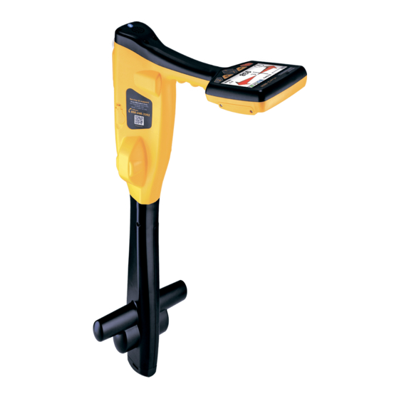
The vLoc3-9800 is a precision location system designed to meet the needs of utility companies and their contractors. In this manual, the vLoc3-9800 Receiver may be referred to as a vLoc3 series, a vLoc3 receiver, receiver, or locator. The following describes the features and use of the receiver:... -
Page 10: Charging The Receiver Batteries
Receiver Charging the Receiver Batteries The vLoc3-9800 can be used with either alkaline batteries or an interchangeable rechargeable battery pack. The central illuminated section within the battery icon indicates the amount of charge remaining. • Green center indicates rechargeable batteries •... -
Page 11: Vloc3-9800 Receiver Keypad
Setup Menu The vLoc3-9800 has several features that can be turned on and off. These features are accessed through the user menu. Switch on the unit by pressing and holding the On/Off key until the start-up screen appears. The start-up screen can be configured to the user's preference and is described later in the manual. - Page 12 Receiver Speaker Volume - Press the enter button to scroll through the speaker volume settings. Backlight - Press the enter button to change the backlight intensity setting. Note that a high backlight setting will affect battery life. Frequency - Use the enter key to enter the Frequency sub-menu. Scroll up and down the table using the"+" and "-” keys. The table contains all available frequency options.
-
Page 13: Self-Test
Receiver Self-Test The vLoc3-9800 has a self-test feature. The test confirms that the equipment is fit for use, and calibration has not drifted from its expected settings. To undertake the test, first find an area free from excessive interference such as overhead fluorescent lighting, large transformers etc. -
Page 14: The Vloc3-9800 Status Bar
Receiver 2.7.1 The vLoc3-9800 Status Bar Along the top right of the displays are the “Status” indicators which will appear at all times. The top left section of the status bar changes depending on which locate mode is being used. The information in the top left section is discussed below in the active and power modes section. -
Page 15: Manual Left/Right Mode (Active Modes Only I.e. Not Available In Power Or Radio Modes)
Receiver 2.7.3 Manual Left/Right Mode (Active modes only i.e. not available in Power or Radio modes) Auto/Manual Indicator Sensitivity Setting Manual 25dB 32.8kHz Moving Pointer Frequency Compass Line direction indicator 0.73m Signal Strength 219mA Depth and Signal current indicator This screen is not available in the Power or Radio passive modes. -
Page 16: Information Pushbutton - Depth & Current
Receiver The Manual Peak Display mode is particularly useful in congested areas where multiple signals are radiating from various lines. The sensitivity is set manually by pressing the “+” and “-” pushbuttons. As the locator is traversed across the target line the “curtains”... -
Page 17: Passive And Active Location
Receiver IMPORTANT When locating a cable or pipe, depth and current measurements should only be taken with the bottom of the receiver standing on the ground directly over and across the target line. When locating a Sonde depth measurements should only be taken with the bottom of the receiver standing on the ground with the blade in-line with the Sonde. - Page 18 Receiver To perform a DFT assessment, verify any nearby transmitters are powered off to avoid additional signal frequency disturbance. Select your preferred frequencies from the frequency menu. These selected frequencies will be assessed in the next few steps. Frequency...
-
Page 19: Active Locating: Applying The Transmitter's Signal
Receiver Although frequency results appear to have less interference, it may not be the best choice to locate certain utilities. These include but are not limited to a conductor, current output, resistance, and signal bleed over adjacent utilities. 2.10 Active Locating: Applying the Transmitter’s Signal... -
Page 20: Transmitter Signal Clamp (For Frequencies Above 8Khz)
Receiver It is sometimes impossible to find a suitable projection to apply the connection clip to a ferrous material. If this is the case use a magnet to contact the line and then clip the red clip to the magnet. A good example of this is to make a connection to a street lighting circuit. -
Page 21: Induction (For Frequencies Above 8Khz)
Receiver When applying a clamp close to a grounding point where multiple grounds or a grounding bus exists ensure that you place the clamp around the target line and not to the ground bus/other grounds. This will help focus the applied signal on the target line. -
Page 22: Locating Active Signals
Receiver Also note that the signal will radiate out to the side of the transmitter as well as below. For this reason, it is recommended that when applying a signal using the induction method, a distance of at least 20m is kept from the transmitter when pinpointing or taking depth readings. -
Page 23: Searching (Sweeping) An Area In The Peak Mode
Receiver With the maximum signal found and the compass running Forward/Backward, the vLoc3 receiver is now directly over the line and exactly across it. If the signal is not distorted, the maximum signal's position will coincide with the position indicated by the arrows. If these two positions do not agree it may be because there is signal distortion. -
Page 24: Tracing A Buried Line
Receiver 2.14 Tracing a Buried Line Where possible trace out from the transmitter connection point. Having pinpointed the line, hold the locator vertically and in front of you with the compass line indicator pointing forward/back. Start by moving the locator left to right/right to left over the line. -
Page 25: Distorted Fields
Switch on the Sonde by connecting the battery. Connect it to the pushrod and place it at the start of the pipe run. Switch on the vLoc3-9800 and select Sonde mode using long presses on the “Return” button. The Sonde icon will now be visible on the screen. - Page 26 Now sweep left and right over the Sonde to obtain a second peak. Note that there are no ghost signals when sweeping left to right over the Sonde. Finally, check that the vLoc3-9800 is in line with the Sonde by rotating its axis to obtain a peak signal. The vLoc3-9800 is now over the Sonde and in line with it.
- Page 27 Receiver If a depth estimation is required, place the vLoc3-9800 on the ground, pinpointing the Sonde above. Momentarily press the “i” button and the depth will be displayed. To exit the depth screen, either wait for the depth screen to “time out” or momentarily press the “I”...
-
Page 28: Data Logging
Data Logging 3. Data Logging The vLoc3 series receivers have internal storage memory that can be used to store locator data. The records are user-initiated and stored whenever the “+” button is pressed in the “Information” screen. Data can be stored relating to a standard locate or receiver accessories apart from the Remote antenna accessory. Each time a self-test routine is run the results are automatically recorded in the equipment. -
Page 29: Bluetooth
Data Logging Delete all logs? Press the “+” key to confirm. Are you sure? Press the “-” key to delete or the “+” key to cancel. Deleting logs..After the deletions are complete, the vLoc3 receiver will return to the locate screen. -
Page 30: Fitting The Bluetooth Module
Data Logging 3.1.1 Fitting the Bluetooth Module Turn the receiver off and remove the battery pack. With a small cross-head screwdriver remove the two screws of the module cover and remove the cover. Remove screws Remove cover The slot on the left is for the Bluetooth module. The slot on the right is not active and is for future developments. Carefully slide the Bluetooth module into the slot and press to secure it in the slot with your thumb. -
Page 31: Transferring Data From The Vloc3 Receiver To A Computer
Data Logging Transferring Data from the vLoc3 receiver to a Computer One method of transferring data is to use the vLoc3 Series Configurator Tool "MyLocator3". This free desktop program can be downloaded from the Vivax-Metrotech website. MyLocator3 Another method to access the locator data is by using the VMMap App which will store all the locator's data in the web portal. -
Page 32: Application Update
Data Logging The MyLocator3 Start Page MyLocator3 can be viewed in several language options. Click on the pull-down menu to select the desired option. 3.3.2.2 Application Update Every time the MyLocator3 Application is started, its version number is checked against the latest version available on the Vivax- Metrotech server. -
Page 33: Toolbar
Data Logging 3.3.3 Toolbar The vLoc3 series receivers can be configured so that features can be switched on or off. Doing this enables the user to tailor the instrument to meet their application's needs while keeping the user interface uncluttered. The toolbar at the top of the screen enables the user to create configurations. -
Page 34: Splash Screen
Data Logging Data Log management screen Before exporting the data use the Log Type dropdown tab to select the type of data required. Options are: Log type dropdown list 3.3.5 Splash Screen An image can be loaded as a splash screen when the locator is turned on in this section. The locator has an LCD screen with a resolution of 480 by 272 pixels. - Page 35 Data Logging The Splashscreen download area To remove a startup screen and revert to the default Vivax-Metrotech screen, click on the “Clear” button and download the cleared screen. The default factory loaded splash Screen ™ Page 29 of 44...
-
Page 36: Frequencies Page
Data Logging 3.3.6 Frequencies Page The “Frequencies” page allows the user to select which frequencies and modes are available when the locator's F-key is pressed and which frequencies appear on the locator's menu. The Frequency page list 3.3.7 Menu Settings The “Menu Settings”... -
Page 37: Advanced Features
Data Logging 3.3.8 Advanced Features The Advanced Features are available to those users in possession of a USB security dongle. If a dongle is attached to the PC, its level will be displayed on the MyLocator3 status bar. Three levels of security come with the dongle. Level one is for the end-user supervisors, level two for Vivax-Metrotech's distributors, repair centers, managers, and level three for Vivax-Metrotech use only. -
Page 38: Loc3 Series Transmitters
Loc3 Series Transmitters 4. Loc3 Series Transmitters This section of the manual covers both the 5-watt and 10-watt Loc3 transmitters. Loc3 Series Transmitter Overview The Loc3 series transmitters are rugged portable transmitters powered by alkaline “D” cells or Li-ion rechargeable batteries. The following describes the features and uses of the transmitter. -
Page 39: Pushbuttons
Loc3 Series Transmitters 4.1.2 Pushbuttons On/Off button Frequency selector Information (Volume, Volts, Ohms, Multi-frequencies LCD Contrast, Receiver Link, Frequency menu and About screen) Output decrease/Navigate through the menu Output increase/Navigate through the menu 4.1.3 Transmitter Information Pushbutton Press the “i " button to access the transmitter settings and menu. Use the “+”... -
Page 40: Transmitter Batteries - Li-Ion And Alkaline
Loc3 Series Transmitters The connection block consists of: • Output connection- 3-pin (XLR socket for direct connection lead and clamp. • Fuse, 1.6A/250V – this protects the transmitter circuitry in the event of the transmitter receiving up to 250V incoming voltage on the output leads, or higher than the allowed current. -
Page 41: Removing And Installing The Battery Tray
Loc3 Series Transmitters WARNING Only use a charger supplied by Vivax-Metrotech Corp. Using non-approved chargers may damage the equipment or overheating/explosion. The rechargeable tray cannot be charged from a 12V DC source. Follow instructions detailed in the General Safety & Care Information section of this manual. Only use the battery charger supplied as using an unapproved charger may damage the battery pack and cause overheating. -
Page 42: Direct Connection Mode
Loc3 Series Transmitters 4.5.1 Direct Connection Mode The Direct Connection mode is automatically selected by plugging a connection lead into the output socket. An icon confirming the direct connection mode is shown on the display. The wave in the icon fluctuates when the transmitter is operating. The direct connection lead consists of two colored cables with clips and covers. -
Page 43: Induction Mode - 5 And 10-Watt Transmitters Only
Loc3 Series Transmitters 4.5.3 Induction Mode – 5 and 10-Watt Transmitters Only The 5 and 10-watt transmitters use an internal antenna to induce a locating frequency onto the target utility. The Induction mode is automatically selected if no connection accessories are plugged into the “output socket.” An icon indicating the “Induction” mode will show on the display. -
Page 44: Most Used Frequencies (Frequency Selection) Feature
Loc3 Series Transmitters As with most manufacturers, signal clamps are tuned to specific frequencies and will not work over the complete range of frequencies. Frequencies are selected by pressing the “f” pushbutton, which toggles through the frequencies available in the current mode's available frequencies. -
Page 45: Multi-Frequency Mode For Direct Connection
Loc3 Series Transmitters About Frequency Menu Receiver Link Disabled LCD Contrast In Clamp Mode Voltage Volume 5 and 10-Watt Transmitters Frequency Menu SD-USA The screen will show a list of frequencies available, with the central one in FF Low a box. FF High 5 and 10-Watt Transmitters You can scroll up or down through the available frequencies by pressing the “+”... -
Page 46: Transmitter Link (Tx-Link)
Loc3 Series Transmitters Multi Freq Setup 32.8kHz Use the “+” and “-” pushbuttons to scroll through the available frequencies and 83.1kHz add the desired frequency in the first box. 200kHz Multi Freq Setup 32.8kHz Press the “f” pushbutton to move the box down and the “+” and “-” pushbuttons 83.1kHz to select the second frequency. - Page 47 Loc3 Series Transmitters R E C E I V E R L I N K D I S A B L E An ID number will now be displayed at the bottom of the screen for B A C K identification purposes.
- Page 48 Loc3 Series Transmitters From this screen, if the link status shows “Connected,” it is possible to: Transmitter Control a. Alter the output level of the transmitter using the “+” and “-” buttons. b. Alter the transmit frequency using the “f” button. Transmitter link status Connected 640 Hz Also shown is the following:...
-
Page 49: Accessories & Options
EMS markers. Once located, the MLA will give the depth of cover to the buried marker with the touch of a button. The MLA attaches to the bottom of vLoc3-Pro, vLoc3-9800, and vLoc3-5000 receivers. When attached and plugged into the receivers, two marker related operating modes are enableds. -
Page 50: Glossary
Glossary 6. Glossary Active Locate A locate where a transmitter is used to apply a signal to a buried pipe or cable, the position of which is then located by a receiver tuned to the same frequency. Active Signal A signal applied by the locator transmitter to a buried line. Typical this is a very precise frequency. Attenuation The reduction of an electromagnetic signal from a pipe or cable. - Page 51 Notes: Vivax-Metrotech Corporation 3251 Olcott Street, Santa Clara, CA 95054, USA Toll Free: 1-800-446-3392 Phone: +1 (408) 734-1400 Website: www.vivax-metrotech.com ™...
Need help?
Do you have a question about the vLoc3-9800 and is the answer not in the manual?
Questions and answers