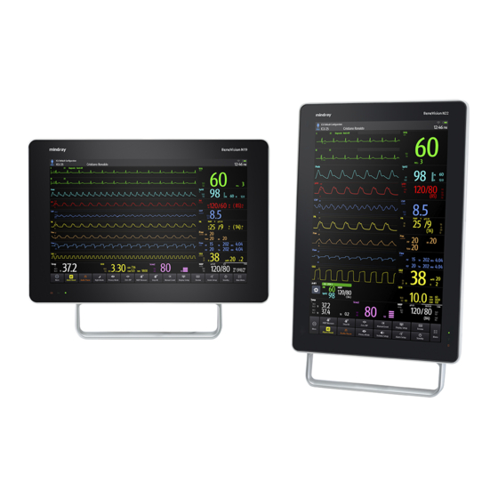
Mindray BeneVision N22 Service Manual
Patient monitor
Hide thumbs
Also See for BeneVision N22:
- Operator's manual (472 pages) ,
- Quick reference manual (40 pages) ,
- Operator's manual (528 pages)
Table of Contents
Advertisement
Quick Links
Advertisement
Table of Contents
Troubleshooting

Related Manuals for Mindray BeneVision N22


Summary of Contents for Mindray BeneVision N22
- Page 1 BeneVision N22/BeneVision N19 Patient Monitor Service Manual...
- Page 3 Copyright 2018 Shenzhen Mindray Bio-Medical Electronics Co., Ltd. All rights reserved. Release time: July 2018 Revision 3.0 BeneVision N22/BeneVision N19 Patient Monitor Service Manual...
- Page 4 This manual may refer to information protected by copyrights or patents and does not convey any license under the patent rights of Mindray, nor the rights of others. Mindray does not assume any liability arising out of any infringements of patents or other rights of third parties.
- Page 5 Mindray’s option, at the factory or at an authorized distributor, for any product which shall under normal use and service appear to Mindray to have been defective in material or workmanship. Recommended preventative maintenance, as prescribed in the service manual, is the responsibility of the user and is not covered by this warranty.
- Page 6 Exemptions Mindray's obligation or liability under this warranty does not include any transportation or other charges or liability for direct, indirect or consequential damages or delay resulting from the improper use or application of the product or the use of parts or accessories not approved by Mindray or repairs by people other than Mindray authorized personnel.
- Page 7 Upon request, Mindray provides circuit diagrams, component part lists, descriptions, calibration instructions, or other information which assist the user’s appropriately qualified technical personnel to repair those parts of the equipment which are designated by Mindray DS USA, Inc. as repairable. Contact Information Manufacturer: Shenzhen Mindray Bio-Medical Electronics Co., Ltd.
- Page 8 This manual is for biomedical engineers, authorized technicians or service representatives responsible for troubleshooting, repairing and maintaining the patient monitors. Contact your local Mindray Service Organization for information on product courses which address service and support for this product. Passwords A password may be required to access different modes within the monitor.
-
Page 9: Table Of Contents
3.4 Module Performance Tests ..................................3-11 3.4.1 ECG Tests ......................................3-11 3.4.2 Resp Performance Test ................................. 3-12 3.4.3 SpO Test ......................................3-12 3.4.4 NIBP Tests ......................................3-12 3.4.5 Temp Test ......................................3-13 3.4.6 IBP Tests ......................................3-13 BeneVision N22/BeneVision N19 Patient Monitor Service Manual... - Page 10 5.3.2 Installing an Secondary Display ..............................5-3 5.3.3 Upgrading Split Unit ..................................5-4 5.3.4 Setting up Wireless Network Functions ........................... 5-4 5.3.5 Upgrading Handle Assembly ............................... 5-4 5.3.6 Installing the Main Unit Battery ..............................5-4 BeneVision N22/BeneVision N19 Patient Monitor Service Manual...
- Page 11 6.7.5 Removing the Pump and Valve..............................6-19 7 Parts ....................................7-1 7.1 Main Unit ........................................... 7-1 7.1.1 Exploded View ....................................7-1 7.1.2 Parts List ....................................... 7-1 7.2 D19 Display Assembly (Capacitive Screen) ............................7-3 BeneVision N22/BeneVision N19 Patient Monitor Service Manual...
- Page 12 A.2 Device Enclosure and Accessories ................................A-1 A.3 Device Labelling ......................................A-2 A.4 Scheduled Electrical Safety Inspection ..............................A-2 A.5 Electrical Safety Inspection after Repair ..............................A-2 A.6 Electrical Safety Inspection Test ................................A-3 BeneVision N22/BeneVision N19 Patient Monitor Service Manual...
-
Page 13: Safety
injury. CAUTION Indicates a potential hazard or unsafe practice that, if not avoided, could result in minor personal injury or product/property damage. NOTE Provides application tips or other useful information. BeneVision N22/BeneVision N19 Patient Monitor Service Manual... -
Page 14: Danger
Refer to Operation Manual for detailed operation and other information. 1.2 Equipment Symbols See the N series Operator’s Manual (P/N: 046-011259-00) for information about the symbols used on this product and its packaging. BeneVision N22/BeneVision N19 Patient Monitor Service Manual... -
Page 15: Operation Theory
These features could better meet the application requirements of high-end users. 2.2 Product System Architecture N22/N19 monitor mainly consists of three parts: main unit, display and module rack. All-in-one installation or split-type installation could be adopted for the main unit and the display. BeneVision N22/BeneVision N19 Patient Monitor Service Manual... - Page 16 The main PCBAs of the system include: Main unit: DCDC and interface board, ACDC board, and main board and interface board. Display: display interface board Module rack: Module rack interface board, and 8-slot module rack communication board. BeneVision N22/BeneVision N19 Patient Monitor Service Manual...
-
Page 17: Functions Of The Main Control Module
As the core control unit of the system, the main board is responsible for such core functions of the system as display, data processing and data storage. The main board also provides high-speed interfaces, such as USB connector, DP interface and network connector. BeneVision N22/BeneVision N19 Patient Monitor Service Manual... -
Page 18: Ac-Dc Module
16V DC input power socket used for connecting to the ACDC board Connector Type B6PH-VS Pin No. Signal Name Signal Direction Function Definition Remarks DC input DC input DC input Ground Ground Ground BeneVision N22/BeneVision N19 Patient Monitor Service Manual... - Page 19 Used for connecting the main board to provide 3.3V, 5V and 16V DC power to the main board. Connector Type 43045-0800 Pin No. Signal Name Signal Direction Function Definition Remarks 3.3V DC output DC output DC output DC output Ground Ground Ground Ground BeneVision N22/BeneVision N19 Patient Monitor Service Manual...
- Page 20 AC availability Ground Battery driven by yellow Battery_Yellow M0_TXD M0 UART sending Battery driven by green Battery_Green M0_RXD M0 UART receiving PWROK Power supply status No signal connection PWR_BTN# Main control startup and BeneVision N22/BeneVision N19 Patient Monitor Service Manual...
-
Page 21: Front Housing Interface Board
As the front housing interface boardhas much to control, a microcontroller unit (MCU) is used for the central control. The MCU is connected to the main control of the system through the DisplayPort AUX channel (DP AUX), and the USB connection channel is reserved. BeneVision N22/BeneVision N19 Patient Monitor Service Manual... -
Page 22: Iview Substrate
(AC or battery), which means that the power management MCU works properly. The display interface board and module rack of the front housing could directly use the system's 12V power supply. BeneVision N22/BeneVision N19 Patient Monitor Service Manual... -
Page 23: The Secondary Screen Of N22/N19 Uses Independent Ac Adapter For Power Supply
The SMR enters the initialization state through the 12V power conversion Handshake would be implemented by the system after 40s, and the connection is established between the front housing, SMR, and the main control BeneVision N22/BeneVision N19 Patient Monitor Service Manual... -
Page 24: Display Signal Flow
DP interface. The front housing interface board converts the DP signals to LVDS signals through the DP conversion chip to drive the display. 2-10 BeneVision N22/BeneVision N19 Patient Monitor Service Manual... -
Page 25: Display Brightness Control
When using AC power supply, the main unit automatically identifies the power switch if the power switches to the battery in case of sudden AC power off. The main unit sends command to the primary screen, and the brightness of the primary screen is set down automatically. BeneVision N22/BeneVision N19 Patient Monitor Service Manual 2-11... -
Page 26: Module Initialization
Query for 1 minute continuously until Module failure success is achieved. Check status self test Status self test succeeded Module failure Parameter configuration Configuration succeeded Module failure The device operates properly 2-12 BeneVision N22/BeneVision N19 Patient Monitor Service Manual... -
Page 27: Testing And Maintenance
(and once a year for CO AG modules). See the following sections for detailed test procedures and contents. BeneVision N22/BeneVision N19 Patient Monitor Service Manual... -
Page 28: Recommended Frequency
Output calibration Performance test NMT tests Sensor check Nurse call relay performance test If the user suspects that the nurse call or analog output does not function properly. Analog output performance test BeneVision N22/BeneVision N19 Patient Monitor Service Manual... -
Page 29: Preventative Maintenance Procedures
Inspect all external connections for loose connectors, bent pins or frayed cables. Inspect all connectors on the equipment for loose connectors or bent pins. Make sure that safety labels and data plates on the equipment are clearly legible. BeneVision N22/BeneVision N19 Patient Monitor Service Manual... -
Page 30: Nibp Tests
Record the current pressure value and meanwhile count time with a timer. Then, record the pressure value after counting to 60 seconds. Compare the two values and make sure the difference is not greater than 6 mmHg. BeneVision N22/BeneVision N19 Patient Monitor Service Manual... - Page 31 You can use an NIBP simulator to replace the squeeze bulb and the reference manometer to perform the test. You can use an appropriate cylinder and a cuff instead of the rigid vessel. BeneVision N22/BeneVision N19 Patient Monitor Service Manual...
-
Page 32: Sidestream And Microstream Co 2 Tests
Check the airway for leak and perform a leakage test as well to make sure that the airway has no leak. Select Main Menu → Maintenance → enter the required password → Module → CO2 → Calibration. Connect the test system as follows: BeneVision N22/BeneVision N19 Patient Monitor Service Manual... - Page 33 Check the airway for leaks and perform a leakage test as well to make sure that the airway has no leakage. Select Main Menu → Maintenance → enter the required password → Module → CO2. In the CO2 menu, select Zero. After the zero calibration is finished successfully, connect the equipment as follows: BeneVision N22/BeneVision N19 Patient Monitor Service Manual...
-
Page 34: Ag Tests
If the calibration is finished successfully, the message Calibration Completed! is displayed in the Calibrate CO2 menu. If the calibration failed, the message Calibration Failed! is displayed. In this case, check whether the operations are correct and perform another calibration. If the calibration fails several times, return the module to Mindray for repair. 3.2.4 AG Tests Leakage Test Plug the AG module into the module rack. - Page 35 Follow this procedure to perform a calibration: Select Main Menu → Maintenance → enter the required password → Module → AG. Check the airway and make sure that there are no occlusions or leaks. BeneVision N22/BeneVision N19 Patient Monitor Service Manual...
- Page 36 If the calibration is finished successfully, the message Calibration Completed! is displayed. If the calibration failed, the message Calibration Failed! is displayed. In this case, perform another calibration. If the calibration fails several times, return the module to Mindray for repair. CAUTION Calibrate the O module, if it has been transported for long distance.
-
Page 37: Power On Test
Compare the amplitude of the square wave with that of the scale. The difference should be with 5%. After completing the calibration, select Stop Calibration. If necessary, you can print out the square wave and wave scale through the recorder and then measure the difference. BeneVision N22/BeneVision N19 Patient Monitor Service Manual 3-11... -
Page 38: Resp Performance Test
Instead, it can only verify that whether the monitor is functional. The accuracy of a pulse oximeter monitor or a SpO sensor needs to be verified by clinical data. 3.4.4 NIBP Tests See section 3.2.23.2.2NIBP Tests. 3-12 BeneVision N22/BeneVision N19 Patient Monitor Service Manual... -
Page 39: Temp Test
Press the Zero key from the IBP menu. Set static pressure to 200 mmHg on the patient simulator. Select Main Menu → Maintenance → enter the required password → Module → IBP. BeneVision N22/BeneVision N19 Patient Monitor Service Manual 3-13... - Page 40 Select the Calibrate button next to the desired IBP channel to start a calibration. If the calibration is completed successfully, the message Calibration Completed! will be displayed. Otherwise, a corresponding message will be displayed. 3-14 BeneVision N22/BeneVision N19 Patient Monitor Service Manual...
-
Page 41: Test
CO waveform and then place the sensor in the air. Check if the alarm message *** Apnea is displayed on the screen. Connect the test system as follows: BeneVision N22/BeneVision N19 Patient Monitor Service Manual 3-15... -
Page 42: Sidestream And Microstream Co Tests
EEG module connects to RL of ECG simulator. The A+ pin of EEG module connects to LA of ECG simulator. The other pins of EEG lead wires connect to any ECG lead as you wish. 3-16 BeneVision N22/BeneVision N19 Patient Monitor Service Manual... - Page 43 Adjust the resistance box to 1 kΩ, verify the resistance value displayed on the monitor is 1kΩ. Test the lead type of the monitor to B+, C+ and D+ respectively instead of lead A+. Set Montage Type: Monopolar Mode , then repeat the step 3~4. BeneVision N22/BeneVision N19 Patient Monitor Service Manual 3-17...
-
Page 44: Bis Test
Connect and set the patient monitor and Vigilance monitor per the procedures in the Operator's Manual. Set the Vigilance monitor to Demo mode. Start the CCO and SvO2 tests in Demo mode. Verify that the CCO/SvO2 numerics displayed on the patient monitor and Vigilance monitor are consistent. 3-18 BeneVision N22/BeneVision N19 Patient Monitor Service Manual... -
Page 45: Nmt Tests
3. Measure the voltage wave of the resistance box by oscilloscope, verify the pulse width is range from 180 to 220us, and calculate the Stimulation Current according stimulation voltage should be range from 33 to 37mA. BeneVision N22/BeneVision N19 Patient Monitor Service Manual 3-19... -
Page 46: Nurse Call Relay Performance Test
Connect the patient simulator to the monitor using an ECG or IBP cable and connect the oscilloscope to the Auxiliary Output Connector of the MPM module of the patient monitor. Verify that the waves displayed on the oscilloscope are identical with those displayed on the monitor. 3-20 BeneVision N22/BeneVision N19 Patient Monitor Service Manual... -
Page 47: Electrical Safety Tests
After the problem is removed, the recorder should be able to work correctly. Switch automatic alarm recording for each parameter ON and then set each parameter's limit outside set alarm limits. Corresponding alarm recordings should be triggered when parameter alarms occur. BeneVision N22/BeneVision N19 Patient Monitor Service Manual 3-21... -
Page 48: Network Print Test
Remove the AC power cord and verify that the patient monitor still works properly. Performance Test Perform the test procedure in the Battery section in the Operator's Manual and verify the operating time of the battery meets the product specification. 3-22 BeneVision N22/BeneVision N19 Patient Monitor Service Manual... -
Page 49: Mounting Check
Check that the VHM bracket can place the monitor at any height as required. Check that the screws on the rotation part of the display are securely installed, and that the damping force is properly set. BeneVision N22/BeneVision N19 Patient Monitor Service Manual 3-23... - Page 50 FOR YOUR NOTES 3-24 BeneVision N22/BeneVision N19 Patient Monitor Service Manual...
-
Page 51: Troubleshooting
4.4 Software Version Check Some troubleshooting tasks may involve software version compatibility. For information about the configuration and software version of your patient monitor, contact Mindray service. To check the software version, do as follows: Select Main Menu quick key, from the System column, select Version. You can check the version information of the system software. -
Page 52: Technical Alarm Check
Arranged according to the possible order BeneVision N22/BeneVision N19 Patient Monitor Service Manual... -
Page 53: Troubleshooting Guide
2. Verify the cables and connectors are not damaged. Power switch & LED board defective Replace the power switch & LED board. Power module defective Replace the power module. Motherboard failure Replace the motherboard. BeneVision N22/BeneVision N19 Patient Monitor Service Manual... -
Page 54: Display Failures
2. Verify the cables and connectors are properly connected Touchscreen control board defective Replace the touchscreen control board. Front housing interface board failure Replace the front housing interface board. BeneVision N22/BeneVision N19 Patient Monitor Service Manual... -
Page 55: Module Rack Failures
12 V. If it is abnormal, the communication module on the SMR fails. Module rack 8-slot communication board Replace 8-slot the module rack communication board. defective DCDC board failure Replace the DCDC board. BeneVision N22/BeneVision N19 Patient Monitor Service Manual... -
Page 56: Alarm Failures
1. Verify the cable connecting the speaker to the connected main board is properly connected. 2. Verify the cables and connectors are not damaged. Speaker failure Replace the speaker. Main board failure Replace the main board. BeneVision N22/BeneVision N19 Patient Monitor Service Manual... -
Page 57: Output Interface Failures
2. If the problem persists, disconnect the AC mains No +5.0 V output for 5s and reconnect it, and then restart the patient monitor. 3. If the problem persists, replace the DCDC interface No +12 V output board. BeneVision N22/BeneVision N19 Patient Monitor Service Manual... -
Page 58: Network Related Problems
Verify the antenna for the MPAN module is installed properly. MPAN module damaged Replace the MPAN module. Satellite module rack (SMR) COM Replace the SMR COM board. board defective Wrong software version for the Upgrade the MPAN module software. MPAN module BeneVision N22/BeneVision N19 Patient Monitor Service Manual... -
Page 59: Device Integration Failures
Upgrade or update the software application of The BeneLink module application The patient monitor has the BeneLink module with the network software is corrupted no response when loading upgrading tool. the ID adapter BeneLink module damaged Replace the module. BeneVision N22/BeneVision N19 Patient Monitor Service Manual... - Page 60 FOR YOUR NOTES 4-10 BeneVision N22/BeneVision N19 Patient Monitor Service Manual...
-
Page 61: Hardware Configuration Options
During removal, note to avoid breaking the connection line by pulling or damaging the connector. Place the removed screws and other parts separately by category so that they can be used in the reinstallation. Do not drop, contaminate or lose them. BeneVision N22/BeneVision N19 Patient Monitor Service Manual... -
Page 62: Optional Parameter Function Modules
115-053716-00 Recorder module You can insert and remove all the parameter modules during patient monitoring. For how to insert and remove parameter modules, see BeneVision N series Patient Monitor Operator’s Manual (PN: 046-011259-00). BeneVision N22/BeneVision N19 Patient Monitor Service Manual... -
Page 63: Optional Functional Assemblies
2D Barcode scanner (support RFID) kit This monitor is configured with wireless network functions and can be connected to network through wireless AP. Contact Mindray Technical Support for assistance in connecting to a network. 5.3.1 Installing an SMR The SMR can be connected to the patient monitor through the SMR connector via the SMR cable. For details, see BeneVision N Series Patient Monitor Operator’s Manual (PN: 046-011259-00). -
Page 64: Upgrading Split Unit
For details, see BeneVision N Series Patient Monitor Operator’s Manual (PN: 046-011259-00). 5.3.4 Setting up Wireless Network Functions Installation and connection to a Wireless Network should be performed by Mindray Service. 5.3.5 Upgrading Handle Assembly Refer to the corresponding section of this manual to install the handle assembly in your patient monitor. -
Page 65: Disassembly And Repair
Before disassembly, make sure that the work surface is clean, smooth and free of debris that could cause damage to the touchscreen. All disassembly and repairs should only be performed by qualified service personnel using anti static precautions. BeneVision N22/BeneVision N19 Patient Monitor Service Manual... -
Page 66: Disassembling Display And Main Unit (Main Unit And Display Integrated Installation)
As shown in the following picture, loosen to remove four M4X55 screws, lift the main unit slowly, disconnect the DP cable, power cable and cord clamp, and separate the main unit from the display. Power Cable M4×55 screw DP Cable Cord clamp BeneVision N22/BeneVision N19 Patient Monitor Service Manual... -
Page 67: Removing Handle/Encoder (Optional Encoder)
As shown in the following picture, remove the Encoder Knob by pushing it off the Encoder shaft from the back with a small punch through the access hole. Use a pair of needle nose pliers to loosen the encoder nut, then remove the encoder. Encoder shaft Encoder knob Access hole BeneVision N22/BeneVision N19 Patient Monitor Service Manual... -
Page 68: Removing Handle Cover
As shown in the following picture, turn the Main Unit over then, loosen and remove the two M3X6 cross recessed pan head screws with pad, disconnect the cable, then remove the cover for separated installation adapter of main unit. Cable M3 screw BeneVision N22/BeneVision N19 Patient Monitor Service Manual... -
Page 69: Installation)
As shown in the following picture, use a flat-bladed screwdriver to pry open the display adapter cover plate, disconnect the power cable and VP (video output) cable, then remove the display interface cover plate. Pry open the gap Cable BeneVision N22/BeneVision N19 Patient Monitor Service Manual... -
Page 70: Disassembling Display (Capacitive Touchscreen)
6.4.1 Removing Display Rear Housing Assembly (D19) As shown in the following picture, loosen and remove the six M3X6 cross recessed pan head screws with pad. M3 screw BeneVision N22/BeneVision N19 Patient Monitor Service Manual... -
Page 71: Removing Display Rear Housing Assembly (D22)
As shown in the following picture, disconnect the switch keypad board cable. cable As shown in the following picture, loosen and remove the two M3X6 cross recessed pan head screws with pad, then remove the switch keypad board assembly. M3 screw BeneVision N22/BeneVision N19 Patient Monitor Service Manual... -
Page 72: Removing Display Interface Board/Touchscreen Panel
M3 screw Cable Cable As shown in the following picture, disconnect the touchscreen cable. Loosen and remove the two M3X6 cross recessed pan head screws, then remove the touchscreen panel. M3 screws Cable BeneVision N22/BeneVision N19 Patient Monitor Service Manual... -
Page 73: Removing Usb Board
Spring screw M3 screw As shown in the following picture, loosen and remove the four M3X6 cross recessed pan head screws with pad, then remove the USB board. M3 screw BeneVision N22/BeneVision N19 Patient Monitor Service Manual... -
Page 74: Removing Led Board/Indicator Board
6.5.1 Removing iView Assembly (iView Assembly Optional) As shown in the following picture, loosen and remove the two M3X6 cross recessed pan head screws with pad, then remove the iView assembly. M3 screw 6-10 BeneVision N22/BeneVision N19 Patient Monitor Service Manual... -
Page 75: Removing Iview Assembly Support Board/Usb Interface Board (Iview Assembly Optional)
USB board; remove the four M3X6 cross recessed pan head screws with pad, then remove the support board. USB board M3 screw Support board 6.5.3 Removing Battery As shown in the following picture, use a flat-bladed screwdriver to remove the battery cover, and then remove the battery. BeneVision N22/BeneVision N19 Patient Monitor Service Manual 6-11... -
Page 76: Removing Acdc Power Board
As shown in the following picture, loosen and remove the four M3X6 cross recessed pan head screws with pad, disconnect the power cable, then remove the ACDC power board. M3 screw Cable 6-12 BeneVision N22/BeneVision N19 Patient Monitor Service Manual... -
Page 77: Removing Dcdc Power Management Board
6.5.6 Removing Antenna Module and Antenna Cable As shown in the following picture, disconnect the antenna cable from the Wi-Fi module, then remove the antenna module and antenna cable. Disconnect the cable Antenna cable Antenna module BeneVision N22/BeneVision N19 Patient Monitor Service Manual 6-13... -
Page 78: Removing Ssd Hard Disk
As shown in the following picture, loosen and remove the four M3X6 cross recessed pan head screws with pad, remove the button battery from it’s holder, then remove the main control board. Cable M3 screw 6-14 BeneVision N22/BeneVision N19 Patient Monitor Service Manual... -
Page 79: Removing Battery Backplane
As shown in the following figure, loosen and remove the eight M3X10 cross recessed countersunk head screws, and remove the hooks. M3X10 screw As shown in the following figure, loosen and remove the three M3×8 cross recessed countersunk head screws, and remove the handle. M3X8 screw BeneVision N22/BeneVision N19 Patient Monitor Service Manual 6-15... -
Page 80: Disassembling The Rear Case Of Module Rack
Loosen and remove the two M3X8 cross recessed pan head screws, disconnect the cable between the interface board and the infrared backplane, and then remove the interface board. M3X8 screw Cable from the interface board of external module rack to the 8-slot board 6-16 BeneVision N22/BeneVision N19 Patient Monitor Service Manual... -
Page 81: Disassembling The Infrared Backplane Of Module Rack
M3X8 cross recessed pan head screws on the infrared backplane, then remove the eight POGO PIN silicon cases of module rack. Module rack antenna M3X6 screw POGO PIN silicon cases of module rack BeneVision N22/BeneVision N19 Patient Monitor Service Manual 6-17... -
Page 82: Disassembling The M51C Module
As shown in the following figure, loosen and remove theparameter board screws, remove the pump and valve cable and NIBP air tube. Then, the parameter board can be removed. Parameter board screws and cable Remove along this direction 6-18 BeneVision N22/BeneVision N19 Patient Monitor Service Manual... -
Page 83: Disassembling The Spo2 Board
NIBP air tube, use a flat-bladed screwdriver to release the clips on the sides of the valve, and then remove the valve assembly. Release the clips Cut the cable ties Disconnect power lines BeneVision N22/BeneVision N19 Patient Monitor Service Manual 6-19... - Page 84 FOR YOUR NOTES 6-20 BeneVision N22/BeneVision N19 Patient Monitor Service Manual...
-
Page 85: Parts
Main unit base assembly 115-037485-00 IVIEW module 115-049593-00 DP port decoration cover 043-005815-01 Small cross recessed pan head screw GB/T823-1988 M2.5X6 plated with green color zinc Rack female receptacle waterproof jacket Power plug anti-pull hook BeneVision N22/BeneVision N19 Patient Monitor Service Manual... - Page 86 Small cross recessed pan head GB9074.5-88 M3X6 with pad and plated with green color zinc Battery cavity assembly Main unit interface adapting assembly Lithium battery 11.3V 5600mAh LI23I003A 115-034132-00 Main unit battery door (overmold) 043-006168-00 BeneVision N22/BeneVision N19 Patient Monitor Service Manual...
-
Page 87: D19 Display Assembly (Capacitive Screen)
009-006879-00 19-inch LCD LVDS signal cable 009-005110-00 1 9inch vertical LED board PCBA 051-001925-01 19 inch horizontal LED board PCBA 051-001924-00 Small cross recessed pan head GB9074.5-88 M3X6 with pad D19 main bracket BeneVision N22/BeneVision N19 Patient Monitor Service Manual... - Page 88 Display interface board and indicator & light sensor 009-005124-00 board line USB interface board PCBA 051-001933-01 Indicator and light intensity sensor board PCBA 051-001918-00 Indicator light lamp shade 049-000872-00 D19 ornamental belt(FRU) 115-045003-00 BeneVision N22/BeneVision N19 Patient Monitor Service Manual...
-
Page 89: D22 Display Assembly (Capacitive Screen)
D22 touchscreen plate -3/ D22 touchscreen adhesive -3 115-045000-00 D22 touchscreen plate -4/ D22 touchscreen adhesive -4 D22 cosmetic gasket Tape for display gasket 0.04 Small cross recessed pan head GB9074.5-88 M3X6 with pad BeneVision N22/BeneVision N19 Patient Monitor Service Manual... - Page 90 009-005104-00 interconnection line Heater fix screw 041-008273-00 Display interface board and indicator & light sensor 009-005124-00 board line USB interface board PCBA 051-001933-01 Small cross recessed pan head GB9074.5-88 M3X6 M04-004012--- with pad BeneVision N22/BeneVision N19 Patient Monitor Service Manual...
-
Page 91: Encoder Assembly
D22 cosmetic gasket 049-000969-01 7.4 Encoder Assembly 7.4.1 Exploded View 7.4.2 Parts List ITEM NO. Description FRU part number D22 knob Encoder interface and keypad board PCBA 115-050303-00 Copper shaft encoder fixing board BeneVision N22/BeneVision N19 Patient Monitor Service Manual... -
Page 92: Module Rack
Interface board PCBA of external module rack 051-001908-00 Module rack cuff bracket 115-033914-00 Rear housing silkscreen of module rack 043-008616-00 Cross recessed pan head screw GB/T818-2000 M3X16 plated with green color zinc Module rack cable hook 115-033911-00 BeneVision N22/BeneVision N19 Patient Monitor Service Manual... -
Page 93: Iview Module
PCBA 051-003028-00 SSD 128GB MLC mSata 023-001329-00 IVIEW rear housing Cross recessed pan head GB9074.5-88 M3X6 with pad and plated with green zinc IVIEW network port insulating sheet Network port insulating sheet BeneVision N22/BeneVision N19 Patient Monitor Service Manual... -
Page 94: Main Unit Separated Installation Auxiliary Accessories
7.7.2 Parts List ITEM NO. Description FRU part number Adapter board mounting bracket Main unit interface adapter board PCBA 051-001915-00 M3X6_GB9074_5 small cross recessed pan head with Adapter board cover of main unit 7-10 BeneVision N22/BeneVision N19 Patient Monitor Service Manual... -
Page 95: Main Unit Base Assembly
Main unit bracket overlay Small cross recessed pan head screw assembly GB/T9074.8 M4X8 plated with green color zinc Small cross recessed pan head GB9074.5-88 M3X6 with pad and plated with green color zinc BeneVision N22/BeneVision N19 Patient Monitor Service Manual 7-11... - Page 96 Grounding pillar Serrated lock washer external teeth GB/T862.2-1987 6 plated with green color zinc Stainless hex nut GB/T6170-2000 M6 passivated Conductive foam 2.0*7.0mm 0.05m AC input to ACDC power cord 009-004993-00 7-12 BeneVision N22/BeneVision N19 Patient Monitor Service Manual...
-
Page 97: Battery Cavity Assembly
7.9.2 Parts List ITEM NO. Description FRU part number Battery cavity 051-001932-00 6600 battery interface board PCBA 043-005814-00 Small cross recessed pan head GB9074.5-88 M3X6 with pad and plated with green color zinc BeneVision N22/BeneVision N19 Patient Monitor Service Manual 7-13... -
Page 98: M51C Module
Hex nut and taper lock washer assembly M3 M04-011002--- M51C module back plane (with IBP/FRU) 051-002383-00-00 Fixing base Cross recessed countersunk head screw GB/T819.1-2000 M3X6 Spanner (T8) Dual module rear housing (M51C) 7-14 BeneVision N22/BeneVision N19 Patient Monitor Service Manual... - Page 99 Filter. Inline Filter43um 1/8”I.D.Tubing 630F flow restrictor Silicone tube Bracket (T8) 043-001964-02 Module waterproof pad (M51C) M51C front panel maintenance package (Masimo 115-057209-00 SpO2/IBP/analog FRU) M51C front panel maintenance package (Nellcor 115-044673-00 SpO2/IBP/analog FRU) 7-15 BeneVision N22/BeneVision N19 Patient Monitor Service Manual...
- Page 100 FOR YOUR NOTES 7-16 BeneVision N22/BeneVision N19 Patient Monitor Service Manual...
-
Page 101: A Electrical Safety Inspection
No physical damage to the enclosure and accessories. No physical damage to meters, switches, connectors, etc. The enclosure and accessories No residue of fluid spillage (e.g., water, coffee, chemicals, etc.). No loose or missing parts (e.g., knobs, dials, terminals, etc.). BeneVision N22/BeneVision N19 Patient Monitor Service Manual... -
Page 102: Device Labelling
Test items: 1, 2, 3, 4, 6, 7, 8 repaired or replaced When both power supply PCBA and patient Test items: 1, 2, 3, 4, 5, 6, 7, 8 electrically- connected PCBA are repaired or replaced BeneVision N22/ BeneVision N19 Patient Monitor Service Manual... -
Page 103: Electrical Safety Inspection Test
NC:100μA, SFC: 500μA Mains on Applied Part Leakage Max: CF applied part: 50μA BF applied part: 5000μA Patient Auxiliary Current Normal condition(NC) Max: CF applied part: NC:10μA, SFC: 50μA BF applied part: NC:100μA, SFC: 500μA BeneVision N22/BeneVision N19 Patient Monitor Service Manual... - Page 104 FOR YOUR NOTES BeneVision N22/ BeneVision N19 Patient Monitor Service Manual...
- Page 105 046-011262-00 (3.0)
Need help?
Do you have a question about the BeneVision N22 and is the answer not in the manual?
Questions and answers