Alfa Laval M15 Manual
Hide thumbs
Also See for M15:
- Instruction manual (46 pages) ,
- Instruction manual (21 pages) ,
- Instruction manual (30 pages)
Table of Contents
Advertisement
Quick Links
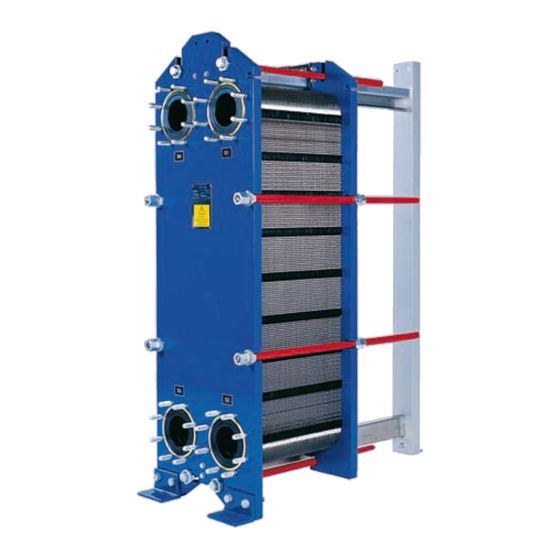
Description
Main components
Frame plate
Tightening bolts
Press the channel
plates together.
Connections
Holes through the
frame plate, permitting
the media to enter into
the heat exchanger.
Threaded studs
around the holes se-
cure the pipes to the
apparatus. Metallic or
rubber-type linings
may be used to pro-
tect the holes against
corrosion.
Channel plates
Heat is transferred from one medium to
the other through the thin channel plates.
The number of plates determines the total
heat transfer surface.
Plate Heat Exchanger
Description
Carrying bar
Carries the channel plates
and the pressure plate.
Protective sheets
Supplied on request.
Pressure plate
Moveable steel plate. In some cases
pipes may be connected to the
pressure plate.
English
Support
column
Bolt
protection
Guiding bar
Keeps the channel
plates in line at their
lower end.
eng
1
Advertisement
Table of Contents

Related Manuals for Alfa Laval M15


Summary of Contents for Alfa Laval M15
- Page 1 Description English Description Main components Carrying bar Carries the channel plates Support and the pressure plate. Frame plate column Tightening bolts Press the channel plates together. Bolt protection Connections Holes through the frame plate, permitting the media to enter into the heat exchanger.
- Page 2 English Description Function The plate heat exchanger consists of a pack of tightening bolts. The plates are fitted with a gasket corrugated metal plates with portholes for the pas- which seals the channel and directs the fluids into sage of the two fluids between which heat transfer alternate channels.
-
Page 3: Installation
Installation English Installation Requirements Multi-pass units: Connections on the pressure plate It is important that the plate pack has been tightened to the correct measurement (check against drawing) before the pipe is connected. Elbow To make it easier to disconnect the plate heat exchanger, an el- bow should be flanged to the connection in the... - Page 4 Installation Lifting Warning! Never lift by the connections or the studs around them. Straps should be used when lifting. Place straps according to picture. MX25, M30, MA30 M15, TL10, T20, TS20 TL35 β β β β β 45° β >45 °...
- Page 5 Installation English Raising Place two timber beams on the floor. Place straps around one bolt on each side. Lift the heat exchanger off pallet using e.g. straps. Lift the heat exchanger off the timber beams. Place the heat exchanger on the timber beams.
-
Page 6: Operation
English Operation Operation Start-up If there is a valve at the exit, make sure it Note! is fully open. If several pumps are included in the sys- tem, make sure you know which one Open the vent and start the pump. should be activated first. -
Page 7: Unit In Operation
Clean and greased No leakage Always consult your local Alfa Laval office for advice on • new plate pack dimensions if you intend to change number of plates • selection of gasket material if operating temper-... -
Page 8: Maintenance
English Maintenance Maintenance Cleaning-In-Place (CIP) The Cleaning-In-Place (CIP) equipment permits Follow the instructions of the CIP equipment. cleaning of the plate heat exchanger without open- ing it. The following CIP models can be used: CIP75, CIP200, CIP400 and CIP800. If CIP cannot be done, cleaning must be per- formed manually, see section “Manual cleaning”... -
Page 9: Manual Cleaning
Maintenance English Manual cleaning Warning! Opening To avoid hand injuries owing to sharp edges, Warning! protective gloves should always be worn when handling plates and protective sheets. If the heat exchanger is hot, wait until it has cooled down to about 40 °C (104 °F). - Page 10 English Maintenance Mark the plate assembly on the outside by The pairs of bolts that are fitted with bear- a diagonal line. ing boxes are opened alternately and diag- onally in two steps, see figures below. Step Bolt No. To dimension 1–2–3–4 1,05A 1–2...
- Page 11 Maintenance English Open the plate pack by letting the pressure plate glide on the carrying bar. If plates are to be numbered, do this before removing the plates. Plates need not to be removed if cleaning is done using only water, i.e. without clean- ing agent.
- Page 12 English Maintenance Manual cleaning of opened units Note! Caution! Be careful not to damage the gasket dur- Never use hydrochloric acid with stainless steel plates. Water of more ing manual cleaning. than 330 ppm Cl may not be used for the preparation of cleaning solutions.
- Page 13 Maintenance English Cleaning agents – Incrustation, scaling Concentration max 4 % Temperature max 60 °C (140 °F) Incrustation – Scaling Sediment Cleaning agent Calcium carbonate Corrosion products Nitric acid Calcium sulphate Metal oxides Sulfamic acid Silicates Silt Citric acid Alumina Phosphoric acid Diatomic organisms and Complexing agents (EDTA, NTA)
- Page 14 English Maintenance Closing Check that all the sealing surfaces are Press the plate assembly together. Tight- clean. ening is done in two steps, see figures be- low. Be careful so that the frame plate and the pressure plate are always in parallel. Brush the threads of the bolts clean, using a steel wire brush.
- Page 15 Maintenance English Max tightening torque • The plate package length at all bolts must not differ more than 1 %. • If the unit does not seal fully, it can be Note! tightened to give dimension A – 1 %. When a pneumatic tightening device is used, The maximum tightening torque must see table below for maximum torque.
-
Page 16: Pressure Test After Maintenance
English Maintenance Pressure test after maintenance Before start-up of production, whenever plates or gaskets have been removed, inserted or ex- changed, it is strongly recommended to perform a pressure test to confirm the internal and external sealing function of the PHE. At this test, one media side at the time must be tested with the other side open to the atmosphere. - Page 17 Maintenance English Regasketing Clip-on gaskets Clip-AD gaskets (MX25) Open the plate heat exchanger according The Clip-AD gasket represents a system with the to page 9, and remove the plate that is to conventional Clip-on fastening around the ports and have a new gasket. fastening by means of adhesive tape along the sides of the plates.
- Page 18 English Maintenance Attach the gasket to the plate. Slip the gas- ket prongs under the edge of the plate. Close the plate heat exchanger according to page 14. Glued gaskets Separate gluing instructions will be delivered to- gether with the glue. Plate Heat Exchanger...
Need help?
Do you have a question about the M15 and is the answer not in the manual?
Questions and answers