
Subscribe to Our Youtube Channel
Related Manuals for Alfa Laval T6 BZM


Summary of Contents for Alfa Laval T6 BZM
- Page 1 Gasketed plate heat exchangers Industrial line – T6–BZM, T6–PZM, T10–BZM, T10–MZM Instruction Manual Lit. Code 200000807-4-EN-GB BRITISH ENGLISH...
- Page 2 © Alfa Laval Corporate AB 2021-04 This document and its contents are subject to copyrights and other intellectual property rights owned by Alfa Laval Corporate AB. No part of this document may be copied, re-produced or transmitted in any form or by any means, or for any purpose, without Alfa Laval Corporate AB’s prior express written permission. Information and services provided in this document are made as a benefit and service to the user, and no representations or warranties are made about the accuracy or suitability of this information and these services for any purpose.
- Page 3 English Italiano Download local language versions of this instruction Scarica la versione in lingua locale del manuale di manual from www.alfalaval.com/gphe-manuals or use istruzioni da www.alfalaval.com/gphe-manuals oppure the QR code utilizza il codice QR. Český 日本の Stáhněte si místní jazykovou verzi tohoto návodu k www.alfalaval.com/gphe-manuals からご自分の言語の...
- Page 4 Slovenski Prenesite različice uporabniškega priročnika v svojem jeziku s spletne strani www.alfalaval.com/gphe- manuals ali uporabite kodo QR. Slovenský Miestne jazykové verzie tohto návodu na používanie si stiahnite z www.alfalaval.com/gphe-manuals alebo použite QR kód. Svenska Ladda ned lokala språkversioner av denna bruksanvisning från www.alfalaval.com/gphe-manuals eller använd QR-koden.
-
Page 5: Table Of Contents
Contents 1 Introduction ........................7 Intended use......................7 Reasonably foreseeable misuses................7 Prior knowledge......................7 Delivered technical information................. 8 Warranty conditions....................8 Advice........................8 Environmental compliance..................9 2 Safety ..........................11 Safety considerations....................11 Definitions of expressions..................11 Personal protective equipment................12 Working at height.....................13 3 Description ........................15 Components...................... - Page 6 6 Maintenance ......................47 Cleaning – Non-product side...................48 Opening........................50 6.2.1 Bolt configuration..................50 6.2.2 Opening procedure..................50 Manual cleaning of opened units................54 6.3.1 Deposits removable with water and brush..........54 Closing........................55 Pressure test after maintenance................58 Regasketing......................59 6.6.1 Clip-on / ClipGrip..................59 7 Storage of the plate heat exchanger ............
-
Page 7: Introduction
The intended use of this equipment is to transfer heat in accordance with a decided configuration. All other use is prohibited. Alfa Laval will not be held responsible for injury or damage if the equipment is used for any other purpose than the intended use described above. -
Page 8: Delivered Technical Information
If faults occur during the specified warranty period, always consult your local Alfa Laval representative for advice. Report to the local Alfa Laval representative, the date when the plate heat exchanger was put into operation . 1.6 Advice Always consult your local Alfa Laval representative for advice on: •... -
Page 9: Environmental Compliance
If there is any uncertainty regarding what material a component is made of, contact the local Alfa Laval sales company. Use a certified (ISO 14001 or similar) scrapping or waste handling company. - Page 10 1 Introduction 200000807-4-EN-GB...
-
Page 11: Safety
2.1 Safety considerations The plate heat exchanger shall be used and maintained in accordance with Alfa Laval’s instructions in this manual. Incorrect handling of the plate heat exchanger may result in serious consequences with injuries to persons and/or property damage. Alfa Laval will not accept responsibility for any damage or injury resulting from not following the instructions in this manual. -
Page 12: Personal Protective Equipment
2 Safety 2.3 Personal protective equipment Protective shoes A shoe with a reinforced toe cap to minimize foot injuries caused by dropped articles. Protective helmet Any helmet designed to protect the head from accidental injury. Protective goggles A pair of tight-fitting eyeglasses worn to protect the eyes from hazards. Protective gloves Gloves that protects the hand from hazards. -
Page 13: Working At Height
Safety 2 2.4 Working at height If the installation requires working at a height of two meters or higher, safety arrangements must be taken in consideration. WARNING Risk of falling. For any kind of work at height, always ensure that safe means of access is available and used. - Page 14 2 Safety 200000807-4-EN-GB...
-
Page 15: Description
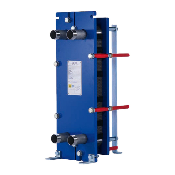
3 Description 3.1 Components Main components 1. Frame plate Fixed plate with a various number of portholes for the connection of the piping system. The carrying and guiding bar are attached to the frame plate. 2. Carrying bar Carries the plate pack and the pressure plate 3. - Page 16 3 Description Connections • Stud bolts Threaded stud bolts around the portholes secure the flange connections to the apparatus. Optional components • Foot Gives stability and is used to secure the plate heat exchanger with bolts to the foundation. • Protection sheets Cover the plate pack and protect against leakage of hot or aggressive fluids and the hot plate pack.
-
Page 17: Name Plate
Description 3 3.2 Name plate The type of unit, manufacturing number and manufacturing year can be found on the name plate. Pressure vessel details in accordance with the applicable pressure vessel code are also given. The name plate is fixed to the frame plate, most commonly, or the pressure plate. - Page 18 3 Description Manufacturer Type Serial No. MANUFACTURER: Year YEAR OF MANUFACTURING: Fluid group TYPE: SERIAL NUMBER: Inlet Outlet Volume → → Allowable press. INLET → OUTLET Min./Max. FLUID GROUP VOLUME Allowable temp. MAX. OP. TEMP. Min./Max. TS ALLOWABLE PRESS. Manufacturer MIN./MAX.
-
Page 19: A Measure
Description 3 3.3 A measure The A measure is the distance from the frame plate (1) to the pressure plate (2). 200000807-4-EN-GB... -
Page 20: Function
3 Description 3.4 Function The plate heat exchanger consists of a pack of corrugated metal plates with portholes for the input and output of the two separate fluids. The heat transfer between the two fluids takes place through the plates. The plate pack is assembled between a frame plate and a pressure plate and compressed by tightening bolts. -
Page 21: Identification Of Plate Side
Description 3 3.5 Identification of plate side The A side of the plates (symmetric pattern) are identified by a stamp with the letter A and the model name at the top of the plate (see the image 1 below). Plates with asymmetric pattern has two possible sides for placement of the gaskets. - Page 22 3 Description 200000807-4-EN-GB...
-
Page 23: Installation
4 Installation 4.1 Before installation, lifting and transport CAUTION Risk of damage to equipment. During installation or maintenance, precautions must be taken to avoid damaging the plate heat exchanger and its components. Damage to components can adversely affect the performance or serviceability of the plate heat exchanger. WARNING Risk of personal injury. - Page 24 4 Installation • Follow the hierarchy specified in this presentation. • Check the condition of the flooring. • Always complete a risk assessment. • Use frames and equipment designed for the task. • Always check the center of gravity before unpacking or moving the equipment.
-
Page 25: Requirements
Installation 4 4.2 Requirements Space See the delivered PHE drawing for actual measurements. 1. Free space is required for lifting plates in and out. 2. Free space is required for removing the tightening bolts. The size is depending on the length of the tightening bolts. 3. - Page 26 4 Installation Avoid excessive loads from the piping system. Required personnel The installation and handling of the plate heat exchanger requires at least two persons. 200000807-4-EN-GB...
-
Page 27: Crate Handling
Installation 4 4.3 Crate handling WARNING Risk of personal injury. Lifting and transport of the crated and uncrated equipment must be carried out by skilled persons. See Prior knowledge in Chapter Preface. The plate heat exchanger is delivered on a pallet and can be packed in a crate or wrapped in stretch film. -
Page 28: Crate - Inspection
4 Installation 4.3.1 Crate — Inspection Examine the outside of the crates before starting to unload and report any transport damage. Contact the insurance company in case of any damages. 4.3.2 Lifting and transportation WARNING Risk of personal injury. The equipment is heavy and sensitive and must be handled with precaution. Unauthorized personnel is not allowed to be in the defined risk area when the crated or uncrated equipment is handled. - Page 29 Installation 4 • Move the crate to its destination. • Lower the crate gently to the floor, leaving enough room around it for easy access to all sides. • Make sure that the crate is firmly supported. Place blocks or plates under it if required.
-
Page 30: Unpacking The Crate
4 Installation 4.4 Unpacking the crate Follow the procedure for the corresponding type of crate:: • Manufactured sides — See Procedure Manufactured sides - Open • Flip box — See Procedure Flip box - Opening • Crafted sides — See Procedure Crafted sides - Opening Unpacking area The minimum unpacking area must be at least twice the size of the largest... -
Page 31: Manufactured Sides - Opening
Installation 4 4.4.1 Manufactured sides — Opening WARNING Risk of personal injury. The equipment or loose objects can fall. Plastic straps may snap when cut off. There can be sharp edges, splinters, and nails on the crate and the equipment. Wear personal protective equipment when handling the equipment during unpacking and installation. -
Page 32: Flip Box - Opening
4 Installation 4.4.2 Flip box — Opening WARNING Risk of personal injury. The equipment or loose objects can fall. Plastic straps may snap when cut off. There can be sharp edges, splinters, and nails on the crate and the equipment. Wear personal protective equipment when handling the equipment during unpacking and installation. -
Page 33: Crafted Sides - Opening
Installation 4 4.4.3 Crafted sides — Opening WARNING Risk of personal injury. The equipment or loose objects can fall. Plastic straps may snap when cut off. There can be sharp edges, splinters, and nails on the crate and the equipment. Wear personal protective equipment when handling the equipment during unpacking and installation. -
Page 34: Inspection After Uncrating
4 Installation 4.4.4 Inspection after uncrating When the equipment is placed in its intended location, always perform the inspections listed below: • Check the A measure. • Make sure that all bolts are properly tightened. • Make sure that the stands and feet are properly tightened. NOTE Some equipment is delivered with the stands disassembled. -
Page 35: Lifting The Equipment
Installation 4 4.5 Lifting the equipment It is recommended to engage the services of a rigging company to take care of all handling related matters until the equipment is in the position where it will be installed. WARNING Risk of personal injury. Equipment is heavy with a centre of gravity placed high. - Page 36 4 Installation β β WARNING Risk of damage to equipment. If lifting is not possible according to this instruction, a risk assessment should be done by authorized personnel. Crated equipment When the equipment is crated it must be lifted in the delivered pallet using a forklift.
- Page 37 Installation 4 Before loosening the equipment from the pallet, secure the equipment from falling using hoist slings. NOTE Do not lift up the equipment and the pallet. Only stretch the hoist slings so the equipment will not fall. Remove any attachment that assembles the equipment with the pallet. Gently lift up the equipment and make sure that it releases from the pallet.
- Page 38 Use of other attachment points or strap load directions than those described are not allowed. If the plate heat exchanger is not supplied with lifting devices from Alfa Laval, the corresponding equipment must be selected and the same attachment points must be used. The authorized personnel have full responsibility for selecting components and procedures in a safe and correct way.
-
Page 39: Raising
Installation 4 4.6 Raising This instruction is valid when raising the plate heat exchanger after delivery from Alfa Laval. Only use a strap approved for the weight of the plate heat exchanger. Follow the principle of the instruction below. CAUTION Risk of damage to equipment. - Page 40 4 Installation Lift the plate heat exchanger off the timber beams. Lower the plate heat exchanger into a horizontal position and place it on the floor. 200000807-4-EN-GB...
-
Page 41: Inspection Before Installation
Installation 4 4.7 Inspection before installation When the equipment is placed in its intended location, always perform the inspections listed below: • Check the A measure. • Make sure that all bolts are properly tightened. • Make sure that the stands and feet are properly tightened. •... - Page 42 4 Installation 200000807-4-EN-GB...
-
Page 43: Operation
5 Operation 5.1 Start-up During the start-up, check that there are no visible leakages from the plate pack, valves or piping system. CAUTION Before pressurizing the plate heat exchanger, it is important to ensure that the temperature of the plate heat exchanger is within the temperature range as stated in the PHE drawing. - Page 44 5 Operation If there is a vent valve installed at the exit, make sure it is fully open. Increase the flow rate slowly. Open the air vent and start the pump. Open the valve slowly. NOTE Avoid rapid temperature changes in the plate heat exchanger.
-
Page 45: Unit In Operation
Operation 5 5.2 Unit in operation Adjustments of flow rates should be made slowly in order to protect the system against sudden and extreme variations of temperature and pressure. During operation, check that media temperatures and pressures are within the limits stated on the name plate and the PHE drawing. - Page 46 5 Operation 200000807-4-EN-GB...
-
Page 47: Maintenance
Different methods can be used for cleaning (see Procedure Cleaning – Non- product side on page 48) or reconditioning can be performed at an Alfa Laval service center. After a long period of use, it can be required to regasket the plate heat exchanger. -
Page 48: Cleaning - Non-Product Side
Personal protective equipment in Chapter Safety. CIP equipment Contact an Alfa Laval sales representative for the size of CIP equipment. WARNING Risk of personal injury. The residuals after a cleaning procedure shall be handled according to local environmental regulations. After neutralization most cleaning solutions may be... - Page 49 Maintenance 6 Liquid Description A non-hazardous cleaning agent for the removal of oil, grease or wax deposits. Also AlfaDegreaser prevents foaming when using Alpacon Descaler. AlfaAdd is a neutral cleaning strengthener designed to be used with AlfaPhos, Alfa- Caus and Alfa P-Scale. 0.5–1 vol% is added to the total diluted cleaning solution to AlfaAdd provide better cleaning results on oily and fatty surfaces and where biological growth occurs.
-
Page 50: Opening
During manual cleaning, it is necessary to open the plate heat exchanger to clean the plates. NOTE Before opening the plate heat exchanger, check the warranty conditions. If in any doubt, contact the Alfa Laval sales representative. See Section Warranty conditions in Chapter Introduction. - Page 51 Maintenance 6 Drain the plate heat exchanger. NOTE Avoid vacuum in the plate heat exchanger by opening vent valves. If there are any protection sheets, remove them. Inspect the sliding surfaces of the carrying bar. Wipe the sliding surfaces clean and put grease on them.
- Page 52 6 Maintenance T6 and T10 plate heat exchanger models using divided bars locked by a nut. Remove nuts, guiding bar support foot, outer bar ends, nuts and washers. Reassemble in the following order; outer bar ends, support foot, washers and nuts. NOTE Opening T6 and T10 plate heat exchanger models will wear out the carrying and guiding...
- Page 53 Maintenance 6 CAUTION Risk of personal injury. Plates and protection sheets has sharp edges. Wear personal protective equipment when handling the plates and the protection sheets. See Section Personal protective equipment Chapter Safety. Open the plate pack by letting the pressure plate glide on the carrying bar.
-
Page 54: Manual Cleaning Of Opened Units
6 Maintenance 6.3 Manual cleaning of opened units CAUTION Never use hydrochloric acid with stainless steel plates. Water of more than 330 ppm Cl may not be used in the preparation of cleaning solutions. It is very important that aluminium carrying bars and support columns are protected against chemicals. -
Page 55: Closing
Check that all the sealing surfaces are clean. Brush the threads of the bolts clean, using a steel wire brush or the Alfa Laval thread cleaner. Lubricate the threads with a thin layer of grease, for example Gleitmo 800 or equivalent. - Page 56 6 Maintenance T6 and T10 plate heat exchanger models using divided bars locked by a nut. Remove nuts, washers, guiding bar support foot and outer bar ends. Reassemble in the following order; washers, nuts, outer bar ends, guiding bar support foot, and nuts.
- Page 57 Maintenance 6 Tighten the four bolts (1), (2), (3), (4) evenly until the A measure has been reached. When a pneumatic tightening device is used, see table below for maximum torque. Check the A measure during tightening. Bolt with washer Bolt size 13.5 26.5...
-
Page 58: Pressure Test After Maintenance
Example of a rebuilding is that more number of plates are added to the plate pack. If there is any uncertainty about the testing procedure of the plate heat exchanger, consult an Alfa Laval representative. 200000807-4-EN-GB... -
Page 59: Regasketing
50, and remove the plate that is to have a new gasket. NOTE Before opening the plate heat exchanger, check the warranty conditions. If in any doubt, contact the Alfa Laval sales representative. See Section Warranty conditions in Chapter Introduction. - Page 60 6 Maintenance 200000807-4-EN-GB...
-
Page 61: Storage Of The Plate Heat Exchanger
The crate is not designed to be stacked. Never put a load on top of the crate. Alfa Laval delivers the plate heat exchanger ready to be put into service upon arrival, if nothing else has been agreed. If storing for longer periods of time, such as one month or longer, certain precautions should be made to avoid unnecessary damage to the plate heat exchanger. -
Page 62: Taken Out Of Service
Closing on page 55. 6. Alfa Laval recommends a hydraulic test should be carried out. The media, usually water, should be entered at intervals to avoid sudden shocks to the plate heat exchanger. It is recommended to test up to the Design Pressure.
Need help?
Do you have a question about the T6 BZM and is the answer not in the manual?
Questions and answers