Table of Contents
Advertisement
Quick Links
Advertisement
Table of Contents

Related Manuals for Alfa Laval TE75P231


Summary of Contents for Alfa Laval TE75P231
- Page 1 SSB Retractor Stroke 120 Air-to-Spring Models: TE75P231, TE75P231-04, TE75P251 & TE75P251-04 Covering ▪ Standard Machines ▪ Machines delivered with ATEX Certification in accordance with Directive 94/9/EC IM-TE91A901-EN1 ESE02196 Date of issue: January 19, 2012 First published: January 19, 2012...
-
Page 3: Table Of Contents
Standard Service Kits and Tools .................... 47 How to order Spare Parts and Claim Procedure ..............49 How to contact Alfa Laval Tank Equipment A/S ..............49 EC Declaration of Conformity ....................50 ATEX-Special Conditions for safe use ................... 52... -
Page 5: Introduction
© 2012 Alfa Laval Corporate AB This document and its contents is owned by Alfa Laval Corporate AB and protected by laws governing intellectual property and thereto related rights. It is the responsibility of the user of this document to comply with all applicable intellectual property laws. -
Page 6: Intended Use
This Instruction Manual is published by Alfa Laval Tank Equipment A/S without any warranty. Improvements and changes to this Instruction Manual may at any time be made by Alfa Laval Tank Equipment A/S without prior notice. Such changes will, however, be incorporated in new editions of this Instruction Manual. -
Page 7: Atex Marking
Changes to the machine are not allowed without approval by the person responsible for the ATEX certification at Alfa Laval Tank Equipment A/S. If changes are made – or spare parts other than Alfa Laval original spare parts are used - the EC Type Examination certification (the ATEX Directive) is no longer valid. -
Page 8: Applications
Applications The SSB Retractor can be used to clean from simple tanks and ductwork, to complex process applications with agitators where it is not possible to use fixed spray balls. Applications such as Storage Tanks, Reactors, Mixers and Spray Dryers including Ductwork and Vent Lines can all be cleaned by use of one or multiple SSB Retractor units. -
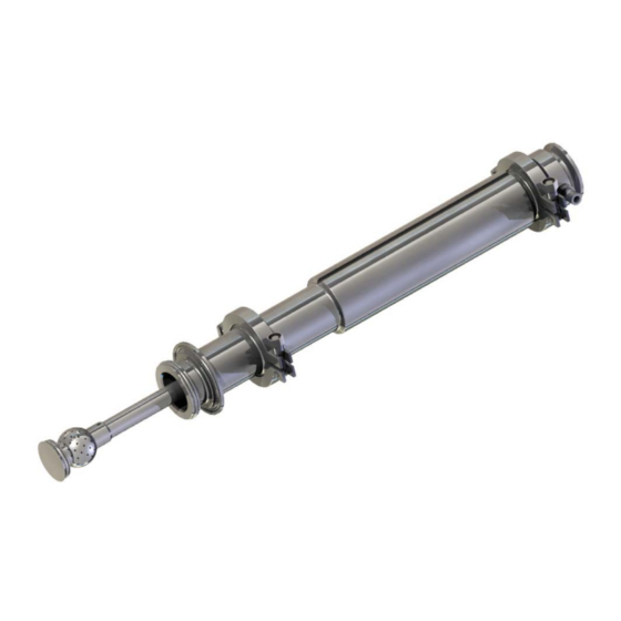
Page 9: Ssb Retractor Unit In Extended Position
SSB Retractor Unit in extended position Figure 1 SSB, extended position Instruction Manual, SSB Retractor - Mini Retract-A-Ball Page 7 Standard machines and machines delivered with ATEX certification in accordance with Directive 94/9/EC IM-TE91A901-EN1... -
Page 10: Accessories
The SSB Retractor is ATEX Category 1 but if sensors are fitted the unit will assume the lower ATEX rating of the Proximity Sensor. If sensors are required for an ATEX environment please consult Alfa Laval. ATEX It is important to note that the SSB Retractor is ATEX Category 1 for installations in Warning: zone 0/20. -
Page 11: Technical Data
Technical Data Model /Article No. TE75P231 TE75P231-04 TE75P251 TE75P251-04 Weight of Unit 3.8kg 3.8kg Operating Air Pressure 3.5-4 bar (50-58 psi) 3.5-4 bar (50-58 psi) Cleaning Fluid Pressure 2 - 4 bar (29 - 58 psi) 2 - 4 bar (29 - 58 psi) Flow Rate Approx. -
Page 12: Available Add-Ons (Documentation)
Technical Data (continued) Available add-ons (documentation) TE75P2X1-70 EPDM + ATEX TE75P2X1-80 EPDM + ATEX + 3.1 cert. TE75P2X1-90 EPDM + 3.1 cert. TE75P2X1-74 FFKM + ATEX TE75P2X1-84 FFKM + ATEX + 3.1 cert. TE75P2X1-94 FFKM + 3.1 cert. Explanation to Add-on´s: ATEX includes: ATEX approved machine for use in explosive atmospheres. -
Page 13: Flow Rate Data
Flow Rate Data Retract-A-Ball Flow Rate (Hole Pattern 90 holes @ 1.3 dia.) Inlet Pressure (Bar) The above Flow Chart shows the typical flow rate through the SSB Retractor fitted with a standard spray ball with 90 holes at 1.3mm dia. Flow Rates can be changed by different drilling patterns if required. -
Page 14: Installation Dimensions And Connections
Installation dimensions and connections Dimensions Figure 2 Dimensions Page 12 Instruction Manual, SSB Retractor - Mini Retract-A-Ball Standard machines and machines delivered with ATEX certification in accordance with Directive 94/9/EC IM-TE91A901-EN1... - Page 15 Installation dimensions and connections NOTES: 1.MATERIALS: MACHINED COMPONENTS: STAINLESS STEEL - GRADE 316L 2. SEALS: MACHINED CARBON FILLED PTFE, EPDM or ISOLAST O-RINGS 3. SPRING: STAINLESS STEEL - GRADE 301S81 (NON-WETTED) 4. BODY JOINTS: DIN 40 FLANGES. DESIGNED IN ACCORDANCE WITH DIN 32676. (SAFETY CLAMPS) 5.
-
Page 16: Installation
Installation The SSB Retractor is mounted to a 2" ISO Ferrule using the 2" ISO gasket and clamp supplied. The unit must be mounted so that it is a minimum for 5º above horizontal. This is important to allow the Home Chamber to drain when cleaning has finished. See Figure 4 . Image Shows unit mounted to a vertical duct. -
Page 17: General Safety And Installation Instructions
Installation (continued) General Safety and Installation Instructions Note: The machine shall be installed in accordance with national regulations for safety and other relevant regulations and standards. Precautions shall be made to prevent starting of the cleaning operation, while personnel are inside the tank or otherwise can be hit by jets from the nozzles. -
Page 18: Special Conditions For Safe Use In Accordance With The Atex Certification, Directive 94/9/Ec
Installation (continued) Special Conditions for Safe Use in accordance with the ATEX Certification, Directive 94/9/EC ATEX The unit shall be connected to a fully earthed pipeline/duct or tank/vessel. Warning: ATEX The pipeline/duct shall not exceed a diameter of 3m, and the tank/vessel shall not Warning: exceed 100m³. - Page 19 Installation (continued) Special Conditions for Safe Use in accordance with the ATEX Certification, Directive 94/9/EC - Continued. ATEX Do not allow the unit to be operated when process media is in the pipeline or tank. Warning: ATEX Do not allow the air pressure to exceed 5.5 bar. Warning: ATEX Do not allow the cleaning media to exceed 4 bar.
- Page 20 Installation (continued) Special Conditions for Safe Use in accordance with the ATEX Certification, Directive 94/9/EC –(c ontinued) Temperature ATEX Atmosphere/surface temperature: Warning: In potentially explosive atmospheres, the temperature must not exceed the maximum surface temperature according to the temperature class for the combustible gas or liquid.
- Page 21 Installation (continued) Orientation As the Spray Ball on the SSB Retractor is often targeted it is important that the unit is installed in the correct orientation. The Spray balls are keyed to the Home Chamber. The Home Chamber has a roll pin fitted through its side.
-
Page 22: Warnings
Installation (continued) Cleaning Media The media must be compatible with Stainless Steel 316L, EPDM or ISOLAST and carbon filled PTFE. Normal detergents, moderate solutions of acids and alkaline are acceptable. After Use Cleaning After use the units should always be flushed with fresh water. Cleaning media should never be allowed to dry inside the unit due to possible ‘salting out’... -
Page 23: Service And Repair Of Atex Approved Machines
Service and Repair of ATEX Approved Machines In order to ensure compliance with the ATEX regulations for service and repair in accordance with EN 60079-19, all service and repair of ATEX approved machines should be performed by Alfa Laval Tank Equipment A/S, Ishoej, Denmark. -
Page 24: Component Parts
Component parts List of Parts Model TE75P231 TE75P231-04 TE75P251 TE75P251-04 Pos.no. Ref. No. Ref. No. Ref. No. Ref. No. Description Remarks TE75P526 TE75P526 TE75P526 TE75P526 Body Tube Spare Part TE75P569 TE75P569 TE75P569 TE75P569 Sleeve Spare Part TE75P570 TE75P570 TE75P570 TE75P570... -
Page 25: Parts Drawing
Component parts (continued) Parts drawing Instruction Manual, SSB Retractor - Mini Retract-A-Ball Page 23 Standard machines and machines delivered with ATEX certification in accordance with Directive 94/9/EC IM-TE91A901-EN1... -
Page 26: Maintenance
Maintenance The units are designed to be self cleaning and should require very little or no maintenance between service intervals. The units are a simple design with only the central telescopic bore being wetted. Performance will be effected by contamination from debris or particles where the CIP system is inadequately filtered or swarf in the system after installation. - Page 27 Maintenance (continued) Carefully withdraw the Inlet Adaptor from the Main Body tube. Ensure to be careful & keep the Inlet Adaptor parallel with the Body Tube as it is withdrawn. Two seals will now be visible on the end of the inlet adaptor stem. The larger seal at the end of the inlet adaptor stem is the cleaning media seal and the second smaller seal is an air seal.
- Page 28 Maintenance Continued) Remove the second clamp between the Main Body tube and the Home Chamber and carefully slide the Body Tube from the Piston to reveal the spring. See Figure 10. Figure 10 There is another Solid Gasket Spacer Ring & two O-rings between the Home Chamber & the Body Tube.
- Page 29 Maintenance (continued) Once the Body Tube is removed the Piston Slide ring will fall away from the Piston. This is normal. See Figure Figure 12 CAUTION: To remove the Piston the Circlip inside the recess of the Piston has to be removed. The Spring is under compression at this stage so the Piston must be held downwards as the Circlip is removed to avoid the Piston being ejected by the spring.
- Page 30 Maintenance (continued) The remaining seal visible on the Piston in Figure is the Main Air Seal. This seal is a PTFE ring with an O-Ring underneath to energise the seal. Figure 14 Look inside the piston, there is an O-Ring which seals the piston to the spray stem. This seal should be carefully removed using a small sharp pointer pressed into the O-Ring.
- Page 31 Maintenance (continued) Remove the spring from the remaining body of the SSB Retractor. Remove the Orientation Screw (if fitted) from the Spray Stem as shown in Figure 8 using a 2.5mm Allen key. Retain the screw as it will be required in the re-build. The Orientation Screw is fitted to ensure the orientation of the spray pattern.
- Page 32 Maintenance (continued) Once the orientation screw is removed, push the spray stem forward to reveal the spray ball. The Sprayball is retained by a 2mm diameter pin which passes through the neck. Straighten the end of the pin with a pair of pliers. See Figure 17. Figure 17 Once the Pin is removed the Sprayball can be unscrewed (anti clockwise) &...
- Page 33 Maintenance (continued) The spray stem can now be drawn out of the main housing. See Figure 19. Figure 19 To remove the sleeve from the main housing the 3mm dia. roll pin should be driven into the housing using a 2.5mm pin punch. (When rebuilding, a new pin must be used.) See Figure 20. Figure 20 Instruction Manual, SSB Retractor - Mini Retract-A-Ball Page 31...
- Page 34 Maintenance (continued) Remove the Sleeve from the main housing to reveal the O-Ring seal. This seal should be carefully removed with a small pair of long nosed pliers & discarded. See Figure 21. Figure 21 The product seal can be seen in the large end of the sleeve. This Seal should be carefully removed using a pair of long nosed pliers &...
-
Page 35: Re-Build & Fitment Of New Service Repair Kit
Re-Build & fitment of New Service Repair Kit The Service Repair Kit for the SSB Retractor unit is- TE75P287-90 for standard EPDM seals. For units TE75P231 & TE75P251 TE75P287-94 for Perfuorolastomer seals. For units TE75P231-04 & TE75P251-04 Both of the above will also require a Seal Installation Tool Kit to help fit the seals TE75P299 - Seal Installation Tool Kit. - Page 36 Re-Build & fitment of New Service Repair Kit (continued) Carefully hold the Inlet Adaptor Body in soft jaws in a vice & using a 13mm spanner unscrew the Inlet Adaptor Stem (anti clockwise). The end of the stem is fitted with an O-ring. Remove the O-ring & thoroughly clean around the O-ring groove.
- Page 37 Re-Build & fitment of New Service Repair Kit (continued) Place the Air Seal Fitment Tool Part TE75P593 over the end of the Inlet Adaptor Stem as shown Figure below in This will allow the Air Seal part No. TE75P518 to be slid over the tool & into position on top of the Energising O-ring.
- Page 38 Re-Build & fitment of New Service Repair Kit (continued) This process will stretch the seal & it will appear to be too big. Remove the tools & begin squeezing the seal with fingers to reduce its size. Move around the seal several times with fingers until the seal has returned almost to its original size.
- Page 39 Re-Build & fitment of New Service Repair Kit (continued) Fitting of Stem Product Seal Part No. TE75P543 Place the Stem Product Seal in the end of the Sleeve. Position the seal so that one side of the seal enters the seal groove. Carefully work around the seal, pushing it into the groove. Care must be taken not to kink the seal.
- Page 40 Re-Build & fitment of New Service Repair Kit (continued) Fitting the Sleeve into the Home Chamber. Lightly wet the O-ring on the Sleeve with clean water & offer up to the Home Chamber. Rotate the Sleeve until the 3mm Spring Pin hole aligns with the hole on the Home Chamber. Push the Sleeve into the Home Chamber &...
- Page 41 Re-Build & fitment of New Service Repair Kit (continued) Fitting the Spray ball to the Spray Stem. Ensuring it is clean, gently screw the Spray Ball all the way onto the Spray Stem. Slowly back off the ball on the thread until the small slot in the neck of the ball aligns with the hole in the Spray Stem.
- Page 42 Re-Build & fitment of New Service Repair Kit (continued) Fitting the Spring. Push the Spray Stem up so that the Spray Ball enters the Home Chamber. If the Orientation Screw is required (if a targeted spray pattern is being used) rotate the Spray Stem until the M3 thread is visible through the guide slot in the Sleeve &...
- Page 43 Re-Build & fitment of New Service Repair Kit (continued) Fitting the Piston/Stem Seal Part No. TE75P541 or TE75P575. Fit the Piston/Stem Seal into the Internal O-ring groove inside the bore of the Piston. See Figure 38. Figure 38 Fitting Piston Seal & Energising O-ring Parts TE75P515 & TE75P516 or TE75P546. Put one side of the O-ring (TE75P516 or TE75P546) into the O-ring groove of the Piston &...
- Page 44 Re-Build & fitment of New Service Repair Kit (continued) Fitting the Piston. Stand the Retract-A-Ball assembly on the face of the Home Chamber so that the Spring points upwards. Place the Piston Spacer onto the Spring as shown. Place the Ring Magnet onto the Spring Spacer if required.
- Page 45 Re-Build & fitment of New Service Repair Kit (continued) Place the Piston onto the Piston Spacer & push downwards, compressing the Spring so that the Spray Stem enters the Piston. Push down until the Piston is fully seated. Warning: DO NOT LET GO OF THE PISTON AS THE SPRING IS UNDER COMPRESSION. Fit a new Circlip Part No.
- Page 46 Re-Build & fitment of New Service Repair Kit (continued) Ensure the Body Tube is clean & check the internal bore for scratches as this bore forms the air seal with the Piston. Carefully lower the Body Tube over the Piston & Air Seal, take great care not to damage the Air Seal.
- Page 47 Re-Build & fitment of New Service Repair Kit (continued) Carefully align the end of the Inlet Adaptor Stem in the end of the Spray Stem & push down. Ensure that both seals on the Inlet Adaptor Stem pass in the Spray Stem & do not snag. See Figure 45.
- Page 48 Re-Build & fitment of New Service Repair Kit (continued) Fitting the Home Chamber Spigot Seal Part No. TE75P538 (EPDM) or TE75P508 (Isolast) Carefully fit the O-ring in the O-ring groove at the front of the Home Chamber. See Figure 46. Figure 46 Test the Unit after Re-build.
-
Page 49: Standard Service Kits And Tools
The Standard Service Kit seal materials are EPDM and carbon filled PTFE. Standard Service Kit for Units TE75P231 & TE75P251, Part No. TE75P287-90 Part No. - Page 50 Standard Service Kit for Units TE75P231-04 & TE75P251-04 “Special Trim” Part No. TE75P287-94 Part No. Description Qty. TE75P551 External Circlip TE75P552 Spring Pin TE75P508 Home Chamber/Spigot Seal (Isolast) TE75P509 Home Chamber/Stem Seal (Isolast) TE75P550 Gasket-Home Chamber TE75P543 Stem Product Seal...
-
Page 51: How To Order Spare Parts And Claim Procedure
Body of the tank cleaning machine. Claim Procedure In case of failure that needs assistance from Alfa Laval Tank Equipment A/S, it is essential for our evaluation that the problem as well as the working conditions of the machine are described as detailed as possible. -
Page 52: Ec Declaration Of Conformity
EC Declaration of Conformity Manufacturer: Alfa Laval Tank Equipment A/S Address: Baldershoej 19, DK-2635 Ishoej Phone: +45 43 55 86 00 Fax: +45 43 55 86 01 E-mail: tankequipment.info@alfalaval.com herewith declare that the below mentioned product: SSB Retractor Stroke 120 Air-to-Spring... - Page 53 EC Declaration of Conformity The ATEX-Directive: DS/EN 1127-1, DS/EN 13463-1, DS/EN 13463-5 DS/EN ISO/IEC 80079-34, Annex A, paragraph A.5.3 Rotating machines ATEX Certification: Baseefa11ATEX0231X EC Type Examination Certificate no. Marking: II 1GD c T(Variable) Tamb -10°C to +140°C II 1GD c T(Variable) Tamb -10°C to +180°C Note: (T)ambient rating: -10°C to +140°C when fitted with EPDM seals -10°C to +180°C when fitted with Perfluorolastomer seals.
-
Page 54: Atex-Special Conditions For Safe Use
ATEX-Special Conditions for safe use ATEX CERTIFICATION II 1GD c T(Variable) Tamb -10°C to +140°C II 1GD c T(Variable) Tamb -10°C to +180°C BASEEFA CUSTOMER REFERENCE No. 5322 PROJECT FILE No. 11/0682 Special Condition for Safe Use 1. The Unit shall be connected to a fully earthed pipeline/duct or tank/vessel. 2. - Page 55 © Alfa Laval Corporate AB This document and its contents is owned by Alfa Laval Corporate AB and protected by laws governing intellectual property and thereto related rights. It is the responsibility of the user of this document to comply with all applicable intellectual property laws. Without limiting any rights related to this document, no part of this document may be copied, reproduced or transmitted in any form or by any means (electronic, mechanical, photocopying, recording, or otherwise), or for any purpose, without the expressed permission of Alfa Laval Corporate AB.
Need help?
Do you have a question about the TE75P231 and is the answer not in the manual?
Questions and answers