Table of Contents
Advertisement
CONTENTS
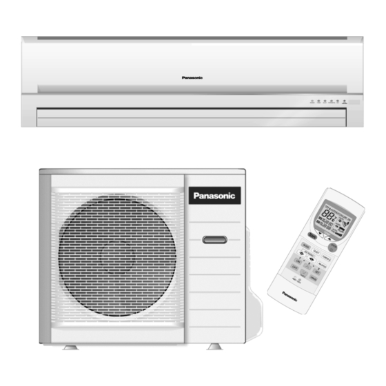
CS-A18DKD CU-A18DKD
CS-A24DKD CU-A24DKD
Page
2
3
3
4
5
6
6
8
10
10
11
12
13
14
15
© 2004 Panasonic HA Air-Conditioning (M) Sdn Bhd
(11969-T). All rights reserved. Unauthorized copying
and distribution is a violation of law.
Order No. MAC0501007C3
Air Conditioner
Page
15
16
17
18
19
26
28
28
29
30
30
32
33
34
34
Advertisement
Table of Contents


Need help?
Do you have a question about the CS-A18DKD and is the answer not in the manual?
Questions and answers