Table of Contents
Advertisement
CONTENTS
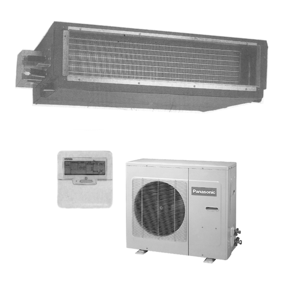
CS-A18BD3P CU-A18BBP5
CS-A18BD3P CU-C18BBP5
Page
3
4
7
8
9
11
22
24
25
26
28
29
30
© 2002 Matsushita Industrial Corporation Sdn. Bhd.
(11969-T). All rights reserved. Unauthorized copying
and distribution is a violation of law.
ORDER NO. MAC0208031C8
AIR CONDITIONER
Page
31
33
36
37
38
39
45
46
50
51
52
58
59
Advertisement
Table of Contents

Related Manuals for Panasonic CS-A18BD3P


Summary of Contents for Panasonic CS-A18BD3P
-
Page 1: Table Of Contents
ORDER NO. MAC0208031C8 AIR CONDITIONER CS-A18BD3P CU-A18BBP5 CS-A18BD3P CU-C18BBP5 CONTENTS Page Page 1 SERVICE INFORMATION 14 COMPONENT SPECIFICATION 2 FEATURES 15 CAPACITY AND POWER CONSUMPTION 3 SPECIFICATION (HEAT PUMP TYPE) 16 DISCHARGE AND SUCTION PRESSURE 4 SPECIFICATION (COOLING ONLY TYPE ) - Page 2 27 INSTALLATION (INDOOR UNIT) 29 REPLACEMENT PARTS 28 INSTALLATION (OUTDOOR UNIT)
-
Page 3: Service Information
1 SERVICE INFORMATION Caution: Pb free solder has a higher melting point than standard solder; Typically the melting point is 50 - 70°F (30 - 40°C) higher. Please use a high temperature soldering iron. In case of the soldering iron with temperature control, please set it to 700 ± 20°F (370 ± 10°C). -
Page 4: Features
2 FEATURES 2.1. Variety of excellent features 2.1.5. Quiet operation • • • • The sound level is as low as 33db (A) for 2.0 HP. The 2.1.1. Compact design, height 27 cm models is ideal for installation in offices, shop and houses •... -
Page 5: Additional Refrigerant Charging
2.2.5. Long pipe design 2.2. Greatly improved workability increases system renewal Max piping length: 25 (m) 18BB Height difference/equivalent pipe 20/25 capability length 2.2.1. Pipes that are one size larger can 2.3. A brand-new control method also be connected for renewal using the latest in technology •... -
Page 6: Group Control Equipment
2.3.4. Group control equipment 2.3.5. Twin and Triple operation • • • • Simultaneous air conditioning of wide spaces and corners is possible. Indoor units of different horsepowers and models can even be used in combination. • • • • Master unit and slave-units can be set automatically in twin and triple systems. -
Page 7: Specification (Heat Pump Type)
3 SPECIFICATION (HEAT PUMP TYPE) 3.1 CS-A18BD3P / CU-A18BBP5 ITEM / MODEL Indoor Unit Outdoor unit Main Body CS-A18BD3P CU-A18BBP5 Cooling Capacity 5.00 (BTU/h) (17,100) Heating Capacity 5.60 (BTU/h) (19,100) Refrigerant Charge-less Standard Air Volume for High Medium and Low... -
Page 8: Specification (Cooling Only Type )
4 SPECIFICATION (COOLING ONLY TYPE ) 4.1 CS-A18BD3P / CU-C18BBP5 ITEM / MODEL Indoor Unit Outdoor unit Main Body CS-A18BD3P CU-C18BBP5 Cooling Capacity 5.00 (BTU/h) (17,100) Refrigerant Charge-less Standard Air Volume for High /min Hi 17 Medium and Low Speed... -
Page 9: Technical Drawing
5 TECHNICAL DRAWING CS-A18BD3P OUTSIDE DIMENSIONS... -
Page 11: Circuit Diagram
6 CIRCUIT DIAGRAM... -
Page 22: Operating Instruction
7 OPERATING INSTRUCTION 7.1. Wired Remote Control Name and function of each part... -
Page 24: Refrigeration Cycle
8 REFRIGERATION CYCLE 8.1. Heating Model CS-A18BD3P / CU-A18BBP5 8.2. Cooling Model CS-A18BD3P / CU-C18BBP5... -
Page 25: Operation Range
9 OPERATION RANGE Power Supply The applicable voltage range for each unit is given in “ the following table”. The working voltage among the three phases must be balanced within 3% deviation from each voltage at the compressor terminals. The starting voltage must be higher than 85% of the rated voltage. -
Page 26: Pipe Length
• • • • The piping length exceeds 10 metres. Example : APPLICABLE FOR ALL MODELS CS-A18BD3P Before shipment, this air conditioner is filled with the rated In case of 10 m long pipe (one-way), the amount of refrigerant subject to 10m piping length. (The amount of refrigerant to be replenished is: rated amount of refrigerant is indicated on the name plate.) - Page 27 10.3. Piping installation by existing piping It is possible to use the existing piping by adjusting the refrigerant gas volume. Please do correct piping installation referring to the table below. Standard piping specification Heat pump type Cooling only type Liquid piping Gas piping Gas charge-less length Additional gas volume...
-
Page 28: Operating Characteristic
Fan Motor Fan Motor Voltage Frequency S.C. R.C.(A) IPT(kW) R.C. R.C. (Hz) COOL/HEAT COOL/HEAT (kW) (kW) CS-A18BD3P 7.9 / 7.9 1.74 / 1.72 0.30 0.06 0.50 0.10 CU-A18BBP5 7.7 / 7.7 1.74 / 1.72 0.30 0.06 0.50 0.10 7.6 / 7.6 1.74 / 1.72... -
Page 29: Fan Performance
12 FAN PERFORMANCE CS-A18BD3P Fan Performance Curve... -
Page 30: Safety Device
13 SAFETY DEVICE INDOOR UNIT Indoor unit Model CS-A18BD3P For fan motor protection Internal °C protector (49F) °C For control protection Fuse 3.15 OUTDOOR UNIT Outdoor Unit Heat pump model 50Hz CU-A18BBP5 Cooling only 50Hz CU-C18BBP5 model For Refrigerant Cycle, High Pressure Switch (63H 15.5... -
Page 31: Component Specification
14 COMPONENT SPECIFICATION Compressor Model Heat pump model 50Hz CU-A18BBP5 Cooling only model 50Hz CU-C18BBP5 Compressor Model 2K32C225CUA Compressor Type No. of Cylinders ROTARY Revolution r/min 2,900 Piston Displacement 7.27 Motor Type Starting Method Direct on-line Starting Rated Output Poles Insulation Class Oil Type Charge... - Page 32 Evaporator Models (Cooling Only Model) CS-A18BD3P Tube Material Copper Tube Outer Diameter 9.53 Thickness 0.28 No. of Tubes/Row Fin Material Aluminium Thickness 0.11 Fin Pitch No./inch Fin Surface Louvre-fin Total Face Area 0.218 Evaporator Fan Type Sirocco Fan No./Unit Evaporator Fan motor...
-
Page 33: Capacity And Power Consumption
15 CAPACITY AND POWER CONSUMPTION 15.1. COOLING CAPACITY CURVE, COOLING POWER CONSUMPTION CURVE COOLING CAPACITY CURVE COOLING POWER CONSUMPTION CURVE RATED COOLING CAPACITY, RATED COOLING POWER CONSUMPTION MODEL NAME RATED COOLING STANDARD CAPACITY (kW) POWER CONSUMPTION (kW) CS-A24BD3P/CU-A24BBP5 6.50 2.59 CS-A28BD3P/CU-A28BBP5 7.30 2.69... -
Page 34: Performance Data
15.2. PERFORMANCE DATA Model CS-A18BD3P/CU-A18BBP5, CS-C18BD3P/CU-C18BBP5 COOLING PERFORMANCE Ambient Temperature Air Entering Condenser (°C D.B.) Return 25°C 30°C 35°C 40°C 45°C D.B. W.B. 6.84 5.98 2.09 6.58 5.88 2.25 6.25 5.76 2.39 5.86 5.51 2.55 5.40 5.07 2.68 7.17 5.19 2.25... - Page 35 15.3. HEATING CAPACITY CURVE, HEATING POWER CONSUMPTION CURVE (HEAT PUMP MODEL ONLY) HEATING CAPACITY CURVE HEATING POWER CONSUMPTION CURVE RATED HEATING CAPACITY, RATED HEATING POWER CONSUMPTION MODEL NAME RATED HEATING STANDARD CAPACITY (kW) POWER CONSUMPTION (kW) CS-A24BD3P/CU-A24BBP5 7.10 2.50 CS-A28BD3P/CU-A28BBP5 7.75 2.61 CS-A28BD3P/CU-A28BBP8...
-
Page 36: Discharge And Suction Pressure
16 DISCHARGE AND SUCTION PRESSURE 16.1. SATURATION TEMPERATURE OF DISCHARGE AND SUCTION PRESSURE... -
Page 37: Position Of The Centre Gravity
17 POSITION OF THE CENTRE GRAVITY MODEL NAME OUTSIDE DIMENSIONS NET WEIGHT CENTRE OF GRAVITY WIDTH (mm) DEPTH (mm) HEIGHT (mm) X (mm) Y (mm) Z (mm) CU-A18BBP5 CU-C18BBP5... -
Page 38: Sound Data
18 SOUND DATA... -
Page 39: Twin And Triple
19 TWIN AND TRIPLE 19.1. TWIN 19.1.1. Operation • • • • Simultaneous air conditioning of wide spaces and corners is possible. • • • • Master units and slave-units can be set automatically in twin and triple systems. No address setting is necessary. •... - Page 40 Automatic address setting for twin system Procedure: Turn on the power supply for the indoor and outdoor units. Operation: Automatic address setting will start 10 to 30 seconds after the power supply is turned on, and will be completed after about 1 minute. If the power supplies for the indoor unit and outdoor unit cannot be turned on at the same time, turn on the power supply for the outdoor unit, the indoor unit which is connected to the remote control, and then the other indoor units in that order.
-
Page 41: Piping Connections
• • • • Be sure to set DIP switch 1-8 to ON when setting twin/triple addresses. If DIP switch 1-1 is set to ON without setting 1- 8 to ON also, group addresses will be set instead, and the remote control open circuit error code (F26) will be displayed. Automatic address resetting for twin systems Function •... - Page 42 Installing branch pipes...
-
Page 43: Refrigerant Charging
19.3. Refrigerant charging • • • • For twin- and triple-type systems The pipe length is the total of the branch pipe (L) and the junction pipes (Ia→t Ib→t Ic in order from the thickest diameter)). At point where the pipe length exceeds 30 m, determine the amount of refrigerant for the remaining liquid-side pipe diameters and pipe lengths from the following table in order to charge the system. - Page 44 19.4. Wiring...
-
Page 45: Wiring Mistake Prevention
20 WIRING MISTAKE PREVENTION Improved quality of installation work through adoption of an “Connection error prevention” circuit which prevents wiring mistakes Connection errors with the control wires and the power supply wires will not only contribute to burning-out of the control circuit board, but can also cause large-scale working losses and affect reliability. -
Page 46: Test Operation And Self Diagnosis
21 TEST OPERATION AND SELF DIAGNOSIS (If the phase is reversed, the LED on the printed circuit 21.1. Test operation board will flash.) • • • • Always be sure to use a properly-insulated tool to operate • • • • Check that the voltage is 198 V or higher when starting the the switch on the circuit board. - Page 47 21.3. Test operation using the wired remote control...
- Page 49 Self-diagnosis error code table...
-
Page 50: Setting Of Save Energy And Thermistor Switch
22 SETTING OF SAVE ENERGY AND THERMISTOR SWITCH 22.1. Energy save setting Open the cover remote control unit and confirm the presence of the [ RP1] marking. Energy save setting method should be different for with [ RP1] marking and without [RP1] marking. -
Page 51: Group Control
23 GROUP CONTROL 1 Setting group for 1 remote control unit • • • • When using a remote control thermostat, the thermostat setting is used for all indoor units in the group. • • • • During group control, up to a maximum of 16 indoor units can be connected. (Do not mix heat pump units and cooling only units.) •... -
Page 52: Trouble Shooting
24 TROUBLE SHOOTING If test operation does not proceed correctly section C) Symptom: Carry out test operation after approximately 6 hours have passed Remote control unit . . . Display of “No power supply” since the power was turned on (crankcase heater is energized). If operation is started by using the remote control within 1 minute of NOTE: turning on the power, the outdoor unit settings will not be made... - Page 53 1. The main power is turned on while the transmission connection cord is not connected (open circuit at section wires between the indoor unit(s) are not connected (open circuit at section A) Symptom: Symptom: − − − − Remote control unit . . . Display of “No power supply” Nothing abnormal appears on the remote control −...
- Page 54 1. The main power is turned on while the transmission Symptom: wires between the indoor unit and the outdoor unit are Nothing abnormal appears on the remote control not connected (open circuit at section A) display, and operation of indoor unit. No. 1 and indoor Symptom: unit No.
- Page 55 1. Automatic address setting (no need to have dip-switch set) If the wiring connected properly as above example, the address is set automatically by the main power supply. An indoor unit with remote control will be set as the master. If the power source is installed to indoor units and outdoor separately, turn on the switch as the following procedure: outdoor unit, indoor unit with control, and other indoor units.
- Page 56 1. Automatic address setting (no need to have dip-switch set) If the wiring connected properly as above example, the AC numbers are set automatically by the main power supply. An indoor unit with remote control will be set as the master. If the power source is installed to indoor units and outdoor separately, turn on the switch as the following procedure: outdoor unit, indoor unit with controller, and other indoor units.
- Page 57 Procedures of deleting memory at twin/triple control 2. Set the “ON” position for No. 1 pin to No. 4 pin of dip switch system (DSW1) on indoor unit P.C. board. (No. 8 pin of dip switch (DSW1) should be “OFF” position) 1.
-
Page 58: Emergency Operation
25 EMERGENCY OPERATION Emergency operation Thermistor Cooling mode Heating mode • • • • Emergency operation of outdoor unit Indoor unit Room temperature Fixed at 25°C Room temperature Shorted Open Emergency operation can be carried out by setting the DSW1 switch on the printed circuit board inside the Thermistor Cooling mode Heating mode... -
Page 59: Control
26 CONTROL 26.1. Description of basic Functions 26.1.1. Cooling mode operation time chart (*1) Outdoor unit fan start control during cooling At the start of cooling mode and drying mode operation, the outdoor unit heat exchanger outlet temperature is detected in order to set the fan speed. - Page 60 • • • • The 10-minute countdown is cleared if the compressor stops or if the temperature at the outdoor unit outlet rises to 13.5°C or higher. 26.2. Freezing prevention control 1. Operation During cooling mode operation, after 9 minutes have passed since the compressor turned on, the outdoor units stops operating when the temperature detected by the indoor unit pipe temperature sensor is 2°C or lower.
- Page 61 26.3. Heating mode operation time chart (Heat pump type only) (*2) Outdoor unit fan control during heating mode operation Under conditions when the compressor is on during heating mode operation (except during defrosting and when the liquid bypass valve is on), the outdoor unit fan is controlled by means of input (CN2) indicating whether the contact of the heating pressure switch on the outdoor unit circuit board is open or closed (At the start of heating mode operation, the fan operates at HI speed.) 26.4.
- Page 62 “PREHEAT” appears on the remote control display. (Other displays remain unchanged.) At the indoor unit, the indoor unit fan stops. In addition, during hot starting, the louvre stays at the horizontal position (angle 0°). 3. Cancelling After 1 minute has passed since heating mode operation started, or if the compressor has turned on, hot starting is cancelled when the temperature detected by the indoor unit pipe temperature sensor is 18°C or higher.
- Page 63 < When hot start operation is cancelled by temperature > 26.5. Indoor unit fan control when thermostat is off during heating mode operation When the thermostat of the indoor unit turns off during heating mode operation, the indoor unit fan operates for 2 minutes at LOW and then stops.
- Page 64 (The fan operates at LOW speed for the remainder of the 30 seconds in (1), and then hot start commences.) 26.7. Defrost mode operation time chart 1. Start and completion of defrosting a. Start During heating mode operation (including automatic heating), after the 45-minute defrosting cycle time has passed, defrosting starts if the temperature detected by the outdoor unit heat exchanger outlet sensor is 2°C or lower for a continuous 5-minute period.
- Page 67 4.Thermostat characteristic during cooling mode and heating mode operation. The thermostat on/off characteristic in both operation modes are given in the table below.
-
Page 68: Indoor Unit Fan Control
26.9. Indoor unit fan control 1. Fixing at LO, MED or HI When LO, MED or HI is set, the relay switches and operation is carried out at that setting. 2. Automatic fan speed When set to AUTO, the indoor unit fan operation changes as shown in the table below. 26.10. - Page 70 27 INSTALLATION (INDOOR UNIT)
- Page 87 28 INSTALLATION (OUTDOOR UNIT)
- Page 97 29 REPLACEMENT PARTS 29.1. INDOOR UNIT CS-A18BD3P...
- Page 98 CS-A18BD3P REF. NO. PARTS NAME PARTS NUMBER QUANTITY PER 1 UNIT CS-A18BD3P Cabinet (Bottom) P02-T06820 Drain pan P42-T02900 Evaporator P45-T05610 Distributor ass’y. P45-T07XXX Cabinet (Top) P42-T02930 Filter guide ass’y. P42-T02920 Filter P03-T01390 Duct flange ass’y. (Outlet) P42-T02910 Fan base ass’y.
- Page 99 29.2. OUTDOOR UNIT CU-C18BBP5...
- Page 100 CU-A18BBP5...
- Page 101 CU-C18BBP5 Ref. No. Part Name & Description Part No. BASE PAN ASS’Y CWD50K2076B COMPRESSOR 2K32C225CUA ANTI-VIBRATION BUSHING CWH50055 NUT FOR COMP. MOUNT. CWH4582065 CONDENSER COMPLETE CWB32C1241 TUBE ASS’Y (CAPILLARY TUBE) CWH35K029B CONDENSER SIDE PLATE CWE04111B ACCUMULATOR CWB13K1002 3-WAYS VALVE CWB011125 STRAINER CWB11025 3-WAYS VALVE...
- Page 102 CU-A18BBP5 Ref. No. Part Name & Description Part No. BASE PAN ASS’Y CWD50K2070B COMPRESSOR 2K32C225CUA ANTI-VIBRATION BUSHING CWH50055 NUT FOR COMP. MOUNT. CWH4582065 CONDENSER COMPLETE CWB32C1240 TUBE ASS’Y (CAPILLARY TUBE) CWT01C2585 PIPE HOLDER RUBBER CWG251022 CONDENSER SIDE PLATE CWD911198 TUBE ASS’Y(PRESSURE SWITCH) CWT022228 RECEIVER CWB141004...
Need help?
Do you have a question about the CS-A18BD3P and is the answer not in the manual?
Questions and answers