Advertisement
Advertisement

Subscribe to Our Youtube Channel
Related Manuals for Franklin Electric INLINE 1100 SPECPAK


Summary of Contents for Franklin Electric INLINE 1100 SPECPAK
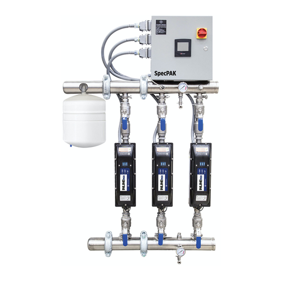
- Page 1 INLINE 1100 SPECPAK Owner's Manual Meets the Requirements of NSF/ANSI 372...
-
Page 3: Table Of Contents
TABLE OF CONTENTS Specifications . . . . . . . . . . . . . . . . . . . . . . . . . . . . . . . . . . . . . . . . . . . . . . . . . . . . . . . . . . . . . . . . . . . . . . . . . . . . . . . . . . . . . . . . 4 Installing the Unit . -
Page 4: Specifications
SPECIFICATIONS Simplex Duplex Duplex Triplex Quad Side View Manifold Overall Site Tank Discharge Suction Width Depth Description Order # Model # Distance Height Connection Capacity Circuit Circuit Flow Boost Volts Pumps Amps Simplex 574705900 1IL-2301414-T1S 12-1/8" 32-1/2" 14-1/2" 47-1/4" 1-1/2" FNPT 2 . -
Page 5: Installing The Unit
INSTALLING THE UNIT 1. Inspecting the Supplied Equipment The package includes the following items: CRATE #1 a . The pre assembled Base Module two pump package with piping, pumps, wire whips, check valves, isolation valves, suction and discharge headers, instrumentation, integral mounting frame, and drain valves . Two additional grooved connections are included to connect the extension header with the Triplex package b . - Page 6 Figure 2 36.13 in QUAD ONLY 25.13 in TRIPLEX ONLY 24.13 in QUAD ONLY 16.00 in 3.20 in 4.00 in 2.70 in DISCHARGE HEADER CONNECTION POINT TO SYSTEM PIPING (REFERENCE POINT FOR LAG BOLT LOCATIONS) 40.98 in 46.89 in DRILLING LOCATION FOR LAG BOLTS (8 FOR DUPLEX, 12 FOR TRIPLEX, 16 FOR QUAD)
- Page 7 3. Mount and Install the Control Panel Unpack the control panel and place the panel on the upper base module discharge header such that the mounting studs on the upper header can pass through the holes located on the bottom of the control panel . Using the hardware found in the accessory kit (remove Hardware Bag #2), place washer, then lock washer and nut on each stud and tighten each nut down firmly .
-
Page 8: Unit Operation
5. Site Piping to the Package Do not over tighten piping connections on the fittings used to connect the site plumbing to each header as this could CAUTION damage the equipment and/or headers . As mentioned earlier, the site water (suction and discharge) can be connected to either end of the suction and discharge manifolds . User installed isolation valves are required near the inlet and outlet to the packaged assembly . - Page 9 Figure 5 PUMP ICONS: Icons for each of the pumps as well as the pump numbers are also shown on the System Screen . The currently designated lead pump has a blue background field behind the Pump # label and the lag pump labels have a white background with green border . The pump icons will change color depending on their current operating status .
- Page 10 COMMISSIONING MODE: Pressing button to the right of the choice menu and selecting “1” will set the system to operate in this mode . As described previously, this will enable the user, on the SYSTEM SCREEN, to toggle pumps ON and OFF to support startup or maintenance activities . The system will also default to this mode when only 1 pump is selected as AVAILABLE .
-
Page 11: Troubleshooting
The user can return to the SETUP PAGE 2 screen by pressing the SETUP PAGE 2 button located at the lower right side of the screen or they can go to the SYSTEM SCREEN . TROUBLESHOOTING Reminder! Use this troubleshooting guide in conjunction with the Franklin Electric Inline Constant Pressure Owner’s Manual to help with resolving operational issues with the package/pumps . - Page 12 Fault Possible Causes Corrective Action Noise in the Discharge Header When Pumps are Operating Air pocket in the discharge header Remove the air in the manner described in the set up instructions . Retighten fittings . When tightening any of the fittings in any one pump circuit, the corresponding fittings in the other circuits must be tightened by an equal number of turns .
- Page 13 Setup Page 2 - Lag Pump Differential Setting and Pressure Transducer Setups While on the system screen press SETUP SETUP PAGE 2 If a 4-20 ma pressure transducer is used in this system and it has an upper pressure other than 150 psi, input the upper pressure range of the transducer (in psi) in this input box.
- Page 14 Setup Page 3 - Pump Boost to Prevent Shut Down Hunting While on the system screen press SETUP SETUP PAGE 2 SETUP PAGE 3 If a pressure boost is desired to prevent potential nuisance shut down hunting, enter the pressure di erential in this field.
- Page 15 Modbus Configuration Item Options Com Port Port 2 Modbus Device ID Selectable: 1-255 Baud Rate Selectable: 9600, 19200, 38400, 57600, or 115200 Data Bits Parity None Stop Bits Standard RS-485 Read Parameters Preset Holding Registers Register 0240h Pressure SP (Pressure SP /10) (Example 800 = 80 .0 PSI) Register 0241h Actual Pressure (Pressure PV / 10) (Example 786 = 78 .
-
Page 16: Replacement Parts
REPLACEMENT PARTS System Replacement Parts... - Page 17 Connections and Major Component List Franklin Electric Inline 1100 Variable Speed Pump 304SS/316SS Discharge Connection 3" Grooved 150# flange - 304SS Inlet Connection 3" Grooved 150# flange - 304SS Control/Electrical Panel 16" x 16" x 6" Touch-screen HMI, lead/lag, alternating pump control Pressure Tank 10 .
-
Page 18: Wiring Diagram
WIRING DIAGRAMS Fuse Table Samba Jumper Settings Fuse Volt Rating Model Size Class Jumper # Setting FU1, FU2 600AC/300DC Bussman FNQ-R-30 30 AMP B (PNP Source all inputs) FU3, FU4 600AC/300DC Bussman FNQ-R-15 15 AMP B (Analog input on input 10) FU5, FU6 600AC/300DC Bussman FNQ-R-15... - Page 19 Subpanel, 10 . 2 x 10 . 2 in, carbon steel Automation Direct or Equal Konnect T-IT KN-G10 Terminal block ground, GRN-YEL 26-10 AWG screw down Franklin Electric Sensata 71CP0350 4-20 MA, 0-150 PSI, 1/4" NPT male, 2 pin packard pressure transducer with cable Thomas & Betts or Equal CC-NPT-38-G Nylon liquid tight cord connector 3/8"...
- Page 20 Fuse Table Samba Jumper Settings Fuse Volt Rating Model Size Class Jumper # Setting FU1, FU2 600AC/300DC Bussman LP J-40SP 40 AMP B (PNP Source all inputs) FU3, FU4 500VAC Bussman FNQ-R-15 15 AMP B (Analog input on input 10) FU5, FU6 500VAC Bussman FNQ-R-15...
- Page 21 9473T69 Terminal block McMaster 9473T143 Terminal block cover plate Franklin Electric Sensata 71CP0350 4-20 MA, 0-150 PSI, 1/4" NPT male, 2 pin packard pressure transducer with cable Thomas & Betts or Equal CC-NPT-38-G Nylon liquid tight cord connector 3/8" NPT...
- Page 22 Fuse Table Samba Jumper Settings Fuse Volt Rating Model Size Class Jumper # Setting FU1, FU2 600AC/300DC Bussman LP J-60SP 60 AMP B (PNP Source all inputs) FU3 to FU10 500VAC Bussman FNQ-R-15 15 AMP B (Analog input on input 10) FU11, FU12 600AC/300DC Bussman LP-CC-5...
- Page 23 9473T69 Terminal block McMaster 9473T143 Terminal block cover plate Franklin Electric Sensata 71CP0350 4-20 MA, 0-150 PSI, 1/4" NPT male, 2 pin packard pressure transducer with cable Thomas & Betts or Equal CC-NPT-38-G Nylon liquid tight cord connector 3/8" NPT...
- Page 24 Form 106983101 9255 Coverdale Road, Fort Wayne, IN 46809 Rev . 001 Tel: 260.824.2900 Fax: 260.824.2909 06/18 www.franklinwater.com...
Need help?
Do you have a question about the INLINE 1100 SPECPAK and is the answer not in the manual?
Questions and answers