Table of Contents
Advertisement
Quick Links
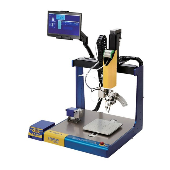
AUTO-SOLDERING SYSTEM
HU-200
Instruction Manual
Thank you very much for purchasing the HAKKO HU-200.
The HAKKO HU-200 is a soldering robot system.
This manual explains how to use the HAKKO HU-200 and the software.
Be sure to read this manual before operating the HAKKO HU-200.
Keep this manual readily accessible for reference.
Advertisement
Table of Contents

Related Manuals for Hakko Electronics HU-200


Summary of Contents for Hakko Electronics HU-200
- Page 1 Thank you very much for purchasing the HAKKO HU-200. The HAKKO HU-200 is a soldering robot system. This manual explains how to use the HAKKO HU-200 and the software. Be sure to read this manual before operating the HAKKO HU-200.
-
Page 2: Table Of Contents
Table of Contents 1. Set Components ........................1 1-1 Packing List .............................. 1 1-2 HAKKO HU-200 ............................2 1-3 Cleaner (CX1003) ............................3 1-4 HAKKO FU-601 ............................3 1-5 Soldering Unit Mount (CX5004) ......................4 1-6 Soldering Unit Fixture Base (CX5002) ....................4 1-7 Cleaner Base (CX5003) .......................... - Page 3 7-1-6 Position ............................51 7-1-7 Settings ............................51 7-1-8 INCHING PITCH/JOG SPEED ....................52 7-1-9 Solder feeding / Solder retraction ....................53 7-1-10 Running Program ......................... 53 7-1-11 Start Button ..........................53 7-1-11-1 Flowchart (Screen Button Operation) ................54 7-1-11-2 Flowchart (Robot Button Operation) ................55 7-2 JOG Operation ............................
- Page 4 Table of Contents (continued) ■ ■ COUNT (Settable range: 1 – 9999999)..............111 7-7-5-2 SOLDER HEAD ADJUST Function ................112 7-7-5-3 SOLDER HEAD ANGLE Function ................113 7-7-5-4 SOLDER UNIT......................113 7-7-5-6 Lang (Change of the language) ................... 114 7-7-5-5 I/O MAPPING ......................114 ■...
-
Page 5: Set Components
1. Set Components 1-1 Packing List Product Name Product Number Configuration Information — p. 2 HAKKO HU-200 (robot) Power cord — p. 2 BX1062 p. 2 USB cable CX1003 p. 3 Cleaner — p. 3 HAKKO FU-601 CX5004 p. 4 Soldering unit mount CX5002 p. -
Page 6: Hakko Hu-200
1. Set Components (continued) 1-2 HAKKO HU-200 HAKKO HU-200 (robot) ..........1 Instruction manual (CD-ROM) ........1 Power cord ..............1 Quick manual (Installation and Connection) .... 1 USB cable (BX1062) ............ 1 Quick user guide (PC software) ......... 1 Solder reel support shaft .......... -
Page 7: Cleaner (Cx1003)
1-3 Cleaner (CX1003) Cleaner (CX1003) ............1 Power cord (for cleaner) ..........1 AC adapter ..............1 Instruction manual (for cleaner) ........1 Cleaner AC adapter Power cord (for cleaner) (CX1003) 1-4 HAKKO FU-601 ............1 Feeder unit attachment screw ........1 HAKKO FU-601 HAKKO FU-6002 (FU6002-01X) ........ -
Page 8: Soldering Unit Mount (Cx5004)
1. Set Components (continued) 1-5 Soldering Unit Mount (CX5004) 1-6 Soldering Unit Fixture Base (CX5002) Soldering unit mount (CX5004) ........1 ....... 1 Soldering unit fixture base (CX5002) 1-7 Cleaner Base (CX5003) 1-8 Feeder Unit (CX5005) ..........1 ..........1 Cleaner base (CX5003) Feeder unit (CX5005) 1-9 PC Tablet PC (Windows 10 Professional) ....... -
Page 9: Specifications
2. Specifications 2-1 Specifications for Each Model 2-1-1 Robot AC100 – 240V 50/60Hz Power supply 300W Power consumption 400 mm 300 mm Movable range (stroke) 200 mm θ ±200° Servo motor Drive system (motor type) θ Solder feed Stepping motor Absolute encoder Position detection method Y (workpiece) 20kg Payload capacity 1 –... -
Page 10: Hakko Fu-601
2. Specifications (continued) 2-1-2 HAKKO FU-601 Station AC 100V 50/60 Hz Power supply 300 W Power consumption 50 – 500 ℃ Settable temperature range Unloaded condition ± 5 °C at idle Temperature Stability AC 29 V Output 145 (W) ×107 (H) ×211 (D) mm Outside dimensions 4 kg Weight... -
Page 11: Part Dimensions
2-2 Part Dimensions 2-2-1 Robot Units: mm Y axis stroke X axis stroke 263.91 Dimensions may vary depending on tip type. 17 mm, 13 mm, 12 mm Z axis stroke 231–261 Center of cleaning position 412–442 Loadable workpiece dimensions according to cleaning position 720 (excluding protective hose for cables on the back side) —... -
Page 12: Jig Table
2. Specifications (continued) 2-2-2 Jig Table Units: mm 81-M4 screws... -
Page 13: Warnings, Cautions And Notes
3. Warnings, Cautions and Notes WARNING In this manual, items requiring caution are classified into 2 categories, “WARNINGS” and “CAUTIONS”, as defined below. Please make sure to understand these items before reading the main text. WARNING: Failure to comply with a WARNING may result in serious injury or death. CAUTION: Failure to comply with a CAUTION may result in injury to the operator, or damage to the objects involved. Indicates important steps or items in the procedure being explained. - Page 14 3. Warnings, Cautions and Notes (continued) WARNING During automatic operation ● Check the safety of the surrounding area before starting operation. ● P rovide indications that the robot is in operation and be careful that no one enters the safety enclosure during operation. ● W hen workers have entered the safety enclosure, take measures to enable emergency stopping. During work ● W hen performing work inside the safety enclosure, notify nearby workers that work is being performed and display a “Working” sign, etc. in an easily visible location. ● W hen work will be performed inside the safety enclosure, before starting work check whether or not external wires are equipped with insulation or shielding, whether or not there are abnormalities in the operation of moving sections, and that there are no abnormalities in the operation of emergency stop equipment, etc. ● W hen training work, inspection, etc. is being performed, be sure that workers perform the work thoroughly. ● T o enable operation to be immediately stopped in the event of a dangerous condition, perform work within reach of an emergency stop button, or install emergency stop devices close at hand.
- Page 15 CAUTION ● S ince the door (cover) of the JOY STICKS may become detached, be careful not to hold onto the door (cover). ● W hen transporting the product, be careful not to hold it by the X axis section. Doing so may result in damage to the product. ● Be sure to ground the product during use. ● A ttach only HAKKO-specified accessories to the robot, and do not use this product for applications other than soldering. ● E nsure safety by wearing a helmet, protective gloves, safety glasses, and safety shoes when necessary. ● Do not subject the product to strong impact. ● P roduct should be installed so that sufficient working space to safely perform preventive maintenance, etc. can be secured. ● Be sure to ground the product during use. ● B e sure to provide sufficient illumination to perform work safely. (JIS Z9110 specifies 300 to 750 lux.) ● B e sure to use the product only in the specified use environment. Use in high- temperature high-humidity regions or in cold high-altitude regions may not provide sufficient performance. ● D o not touch the product with wet hands or use the product when the main body or cords are wet. ● I f the product becomes abnormally hot or emits smoke, abnormal odors, or abnormal noise, stop use immediately and set the power switch to off.
- Page 16 3. Warnings, Cautions and Notes (continued) About Batteries Please be sure to replace batteries before end of service life. The battery will be depleted when all power supply is turned off or the main supply on the back side is turned on and the power supply button on the front panel is turned off. Battery life Approx. 6500 hours (approx. 9 months) Use the above information as a reference for the service life of the battery. However, the duration of the charge varies depending on the use environment and ambient temperature. Batteries (4 pcs.) CAUTION If the battery runs out, the position information for each axis will be lost and the product will not operate normally. Always be sure to have a new battery on hand and replace the battery before it runs out. If battery has run out: If the battery has run out, please consult the sales office or distributor since it will be necessary to set the position information again from the start. Refer to “8-4 How to replace batteries” (p. 129) for the procedure for replacing batteries.
- Page 17 License Agreement Please read this License Agreement before using this product. By using this product, you are deemed to have accepted this License Agreement. If you do not agree with the terms and condition of this License Agreement, you will not be licensed to use this product or Software. HAKKO Corporation (hereinafter referred to as “Licensor”) grants to a customer (hereinafter referred to as “Licensee”) a license to use Software (hereinafter referred to as “Software”) based on the following terms and conditions. 1. Copyright All copyrights associated with Software are reserved by Licensor or granted a right to sublicense to Licensor by a third party. 2. Term • The Agreement shall become effective when Licensee installed or used Software. • T he Agreement recognizes any updates to Software as a part of Software and the terms and conditions of the Agreement shall remain in effect. • Licensee may terminate the Agreement by uninstalling or destroying Software. • I n case Licensee breaches any of the provisions of the Agreement, Licensor may terminate this Agreement immediately without a notice to Licensee. When Licensee receives such notice from Licensor, Licensee shall destroy Software and any of the copies. 3. Grant of License • L icensor hereby grants Licensee a non-exclusive, non-transferrable and non-sublicensable license to use Software under the provisions of the Agreement. • L icensee shall not copy or redistribute Software unless Licensor grants Licensee such license with its prior written consent. • L icensee shall not sell, loan or assign Software to a third party unless all of the obligations under this Agreement are transferred to an assignee or a loaned party.
- Page 18 3. Warnings, Cautions and Notes (continued) 4. Disclaimer • Licensor may modify specification of Software without an advance notice to Licensee. • L icensor may revise the contents of this Agreement without an advance notice to Licensee. In case of such revision, this Agreement becomes invalid and the current Agreement after revision shall be applicable. • L icensor shall not be liable for any damages or lost profit caused to Licensee directly or indirectly from use or inability of this product (including operation of a machine or Software caused from such use). • I n no event, Licensor’s liability on damage caused in association with Software shall exceed the total amount paid to Licensor by Licensee for Software. 5. Miscellaneous This Agreement shall be governed by the laws of Japan, and Osaka District Court shall have exclusive primary jurisdiction with respect to all disputes arising out of this Agreement.
-
Page 19: Part Names
4. Part Names 4-1 Front View Display arm Z axis X axis Solder reel holder Attachment holder Head cover Cleaner base θ axis JOY STICK (for X/Y axes) JOY STICK (for Z/θ axes) Y axis Easy Input Switch Front panel Jig table START/PAUSE/STOP button POWER button Door (cover) Emergency stop button... -
Page 20: Rear View
4. Part Names (continued) 4-2 Rear View Servo motor Cable carrier Cable carrier Servo motor Z axis brake release button Rear panel Z axis brake release button If the Z axis brake release button is pressed while the equipment is in emergency stop condition while the application is running, the solenoid brake will be set to off. -
Page 21: Front Panel
4-3 Front Panel Emergency stop button START/PAUSE/STOP button Easy Input Switch button JOY STICK JOY STICK POWER button (for X/Y axes) (for Z/θ axes) JOY STICK (for X/Y axes) START/PAUSE/STOP button Moves the X axis and Y axis manually. For Runs, pauses, and stops the program. movement direction, refer to the diagram. -
Page 22: Rear Panel
4. Part Names (continued) 4-4 Rear Panel Inlet External I/O connector Power switch Motor connector (main power supply) (for feeder) Relay cord connector (for FU-601) Outlet 1 USB connector Outlet 2 (for cleaner and PC) CAUTION Even if the cable is plugged into a USB connector other than the USB connector for PC (lower right), connection between the PC and robot will not be achieved. -
Page 23: Installation
5. Installation 5-1 Cautions on Installation Install the robot on a level surface. WARNING • W hen transporting the robot, it should be carried by at least 2 people, or a cart, hand truck, etc. should be used. • W hen performing work involving 2 or more people, be sure that the relationship between the leader and subordinates is clear, and perform work while giving voice instructions to each other to ensure safety and prevent dangerous contact or falls. • Secure the robot in place to prevent the robot from tipping over or falling. CAUTION • S ince the door (cover) of the JOY STICKS may become detached, be careful not to hold onto the door (cover). • W hen transporting the product, be careful not to hold it by the X axis section. Doing so may result in damage to the product. 5-2 Attaching Accessories to the Robot At the time of shipment, the robot is as shown below. Be careful not to hold the X axis. -
Page 24: Attaching The Feeder Unit (Cx5005)
5. Installation (continued) 5-2-1 Attaching the Feeder Unit (CX5005) Open the cover of the feeder unit (CX5005), attach Cover Solder feed the solder feed pulley unit to the feeder unit (CX5005), pulley unit and tighten the screws indicated in the diagram. Hexagon socket Tighten head cap screw M3×6 (2) CAUTION... -
Page 25: Attaching The Soldering Iron Unit
5-2-2 Attaching the Soldering Iron Unit Attach the tension springs included with the soldering unit mount (CX5004) to the soldering unit mount. Tension spring (2) Assemble the soldering unit mount (CX5004) using 1 of the hexagon socket head cap screws included with the soldering unit mount. Hexagon socket head cap screw M3×10... - Page 26 5. Installation (continued) About the Soldering Unit Mount (CX5004) The angle of the soldering unit mount (CX5004) for attaching the HAKKO FU-6002 and feeder unit (CX5005) can be changed in 5° intervals. Example: To attach at a 30° angle 30° Spring washer (nominal dia. 6mm) Knock pin Low-profile ø4×8 (2)
- Page 27 Remove the soldering unit fixture base included with the HAKKO FU-601 from the HAKKO FU-6002. HAKKO FU-6002 Cover screw M4×12 (2) Soldering unit fixture base Attach the soldering unit fixture base to the soldering unit mount (CX5004). Hexagon socket head cap screw M4×6 (2) CAUTION Be sure to attach the soldering unit fixture base in the proper orientation.
- Page 28 5. Installation (continued) Attach the tip (sold separately) to the HAKKO FU-6002 included with the HAKKO FU-601. CAUTION Allow the tip to cool before replacing it. When replacing the tip while it is still hot, be sure to use the heat-resistant pad. When replacing the tip, do not touch this screw. 1) Slide the spatter prevention cover forward. 2) Loosen the tip holding screw (M3 × 10). HAKKO FU-6002 3) Insert the tip.
- Page 29 How to Adjust the Tip Position 1. When the tip position adjustment screws are loosened, axis rotation (a) and left/right movement (b) can be performed. Move the tip relative to the target workpiece, and after determining the tip position, tighten the screws. Tip position adjustment screw (a): Axis rotation Hexagon socket head cap screw M3 × 15 Tip position adjustment screw (b): Left/right movement Flange socket M3 ×...
-
Page 30: Attaching Tube Units
Cover screws M4 × 12 (2) 5-2-3 Attaching Tube Units Install the tube unit and solder bobbin on the HU-200 Tube unit (0.3 – 1.0 mm) (BX1055) (1.2 – 1.6 mm) (BX1042) (robot). Install the solder bobbin while paying attention to the solder feed direction. - Page 31 Attach tube unit and tube unit B to the feeder unit Tube unit (0.3 – 1.0 mm) (BX1055) (1.2 – 1.6 mm) (BX1042) (CX5005) and tighten the screws indicated in the diagram. Tighten Tube unit B (0.3 mm) (BX1054) (0.5 – 1.0 mm) (BX1052) (1.2 –...
- Page 32 5. Installation (continued) Open the cable clip on the upper part of the soldering unit fixture base (CX5002), pass the tube unit through the cable clip, and close the cable clip again. Tube unit B (0.3 mm) (BX1054) (0.5 – 1.0 mm) (BX1052) (1.2 –...
- Page 33 — Note — There are 2 kinds of tube units: The tube unit attached between the HAKKO HU-200 (robot) and the feeder unit, and tube unit B attached between the feeder unit and the solder feed guide. There are different models of each kind according to the solder diameter.
-
Page 34: Connecting Cables And Cords
Connecting Cables and Cords Connect the feeder cable (BX1045) between the robot and feeder unit (CX1010), and connect the relay cord (HAKKO HU-200 set) between the HAKKO FU-601 and robot. Connect the soldering iron cable (BX1033) between the HAKKO FU-601 and HAKKO FU-6002. -
Page 35: Mounting And Connecting The Pc
5-2-5 Mounting and Connecting the PC Lift up the top part of the tablet, slide the PC in, and secure it in the tablet holder. Connect the PC and robot with the USB cable (BX1062) and power cord. USB cable (BX1062) Power cord (for PC) Power cord (for cleaner) CAUTION... -
Page 36: Attaching The Cleaner (Cx1003)
When the cleaner is connected to the robot, set the selector switch to “1” and connect as shown in the diagram below. For information on how to use the cleaner (CX1003), refer to the cleaner instruction manual. Selector switch HAKKO HU-200 (robot) 24V output Cleaner (CX1003) -
Page 37: Wiring Of The Cleaner (Cx1003)
5-3-1 Wiring of the cleaner (CX1003) The cleaner wires it like the diagram below. Connect either to Vs of the cleaner (CX1003) side. Rear View Connect to IN of the cleaner (CX1003) side. — Connecting of the lead — Loosen Insert Tighten the screw the lead the screw Pull the lead, and confirm that it is not pulled out. 5-3 External I/O Pin Layout This is the I/O pin layout for input/output with external devices. -
Page 38: Installation
6. Installation You must be logged into the computer with Administrator user rights in order to install the software. 6-1 Performing a New Installation of the Software Double-tap on Select the language to be used for the installation. After selecting the language, tap [OK] to proceed to the installation screen. When the installation screen is displayed, tap [Next]. - Page 39 The End User’s License Agreement will appear. Read the terms of the license agreement carefully and if you agree to the terms, select “I accept the terms in the license agreement” and tap [Next]. CAUTION Installation and use of this software can be performed only by agreeing to this “Software License Agreement”. If agreement to the End User’s License Agreement is not given, this software cannot be used. Tap [Install]. After installation has been completed, tap [Finish].
-
Page 40: Performing A Software Update
6. Installation (continued) 6-2 Performing a Software Update 6-2-1 Backing up Data Back up the data before Updating the software. The backup procedure is as follows: Tap the “This PC” icon on the desktop and open the C: drive. Next, open the HakkoCorporation folder and then open the HAKKO SOLDERING SYSTEM2 folder. Create new folders on the desktop and copy the following two folders as backup data. -
Page 41: After Installation Has Been Completed
After installation has been completed, tap [Finish]. 6-2-3 After Installation Has Been Completed • “ Program” folder After updating, check that there is a “Program” folder under the C:\Hakko Corporation\HAKKO SOLDERING SYSTEM2 folder. If the “Program” folder has been deleted, copy the backup “Program” folder to that location. • “ System” folder Copy the backup “System” folder to under C:\Hakko Corporation\HAKKO SOLDERING SYSTEM2 and overwrite the existing “System”... -
Page 42: Operation
7. Operation First, check that all connections in “5. Installation” have been performed, and then switch on the main power supply and POWER button of the HAKKO HU-200 (robot) and switch on the power of the PC. Main power supply... - Page 43 When the software is started, a window asking whether to return to origin will appear (refer to the diagram below). Tap [OK] to execute return to origin. When [Cancel] is selected, be sure to execute return to origin from [HOME] of the software’s top screen. CAUTION • F irst, check that all equipment have been connected properly and that there is no danger in the surrounding area.
-
Page 44: Explanation Of Software Screen
7. Operation (continued) 7-1 Explanation of Software Screen (10) (11) Software Top Screen (Admin mode) When the software starts up, the top screen including the following information will be shown. Program Settings Cleaning Settings JOG operation settings Soldering Conditions Solder Feed/Solder Back Feed System Settings (10) Program to run Work information... -
Page 45: Program
7-1-1 Program Program List Screen (1) Program (top screen) Used for selecting, editing, or newly creating a work program. (2) OSK Calls up the on-screen keyboard for inputting the program name. (3) Edit Calls up the Program Edit Screen (refer to next page) for the selected program. For details on the Program Edit Screen, refer to “7-5 Creating a Soldering Program”... - Page 46 7. Operation (continued) (10) (11) Program Edit Screen The start point and end point cells and checkboxes can be set directly in the Program Edit Screen. More detailed settings can be performed in the Point Edit Screen which can be called up by double-tapping in the first column or in the STEP column.
- Page 47 (7) Run Selecting the desired program and tapping [Run] will cause the selected program to be shown in the running programs area of the top screen. Error checking will be performed at the same time. If an error such as input of a value outside the range, etc.
- Page 48 7. Operation (continued) (8) COPY: Copies point data. Select the beginning of the row to be copied and tap [COPY]. The data for a single point row will be copied. To select multiple rows, tap and drag on the beginning of the rows. PASTE: Pastes the copied data.
- Page 49 (16) (11) (12) (13) (14) (10) (15) (17) (18) (19) (20) (21) (22) Point Edit Screen Detailed point settings are performed in the Point Edit Screen. (1) STEP = 1 (number) 1 (number) indicates the solder point number. (2) NOTE Comments, memos, etc.
- Page 50 7. Operation (continued) (10) Move Moves to the set Start Pos./OFFSET or end point coordinates. If the value is blank, no movement will be performed. If the end point is blank when the start point is an offset, no movement will be performed even if [Move] on the start point side is tapped because calculation cannot be performed.
-
Page 51: Cleaning Settings
7-1-2 Cleaning Settings (10) (11) Cleaning Settings Screen (1) Cleaning Settings (top screen) Button for setting cleaning settings. Up to 5 settings can be set. (2) Cleaning number Cleaning program number. Up to 5 cleaning programs can be set. (3) Current point Shows the current tip position. -
Page 52: Soldering Conditions
7. Operation (continued) 7-1-3 Soldering Conditions Solder Feed Parameter Setting Screen Solder feed programs are created in the Solder Feed Parameter Setting (1) Soldering Conditions (top screen) Screen. A maximum of 250 solder feed programs can be set. (2) Soldering Feed Program Solder feed program numbers. A single vertical column is a single program. Input the temperature setting. -
Page 53: System Settings
7-1-4 System Settings System Settings Screen (Admin mode) (1) System Settings (top screen) Used for setting more detailed settings. For details, refer to “7-7 Performing Detailed Settings” (p. 94). (2) OTHER OFFSET: Sets the offset when using AUTO SET. Z-ESC: Sets the Z axis lift amount when an error occurs in the HAKKO FU-601 solder feed. COUNT: Sets the numerical value for COUNT DOWN shown in work information in the top screen. -
Page 54: Work Information
7. Operation (continued) 7-1-5 Work Information (5b) (5a) (1) Program name Displays the name of the selected program. When a program name is displayed, the Program Edit Screen for the program corresponding to the name can be opened by double-tapping on the program name. -
Page 55: Position
7-1-6 Position Used for checking the current coordinates of the robot or for performing coordinate movement of the robot. (1) Shows the current coordinate of the robot for each axis. (2) When the coordinates to move to are known, input the coordinates. When [GO] is tapped, the corresponding axes will move to the specified coordinates. -
Page 56: Inching Pitch/Jog Speed
7. Operation (continued) (1a) Z axis absolute lift position (checkbox) Sets the Z axis lift coordinate on and off. Normally, this checkbox is checked. (2) Moving speed Sets the movement speed of each axis for movement between points while the program is being run. (Settable range: 1 –... -
Page 57: Solder Feeding / Solder Retraction
7-1-9 Solder feeding / Solder retraction Buttons for feeding and retracting solder when in manual. The solder feed speed can also be set. For details, refer to “7-1-3 Soldering Conditions” (p. 48), and for operations refer to “7-4 Solder Installation and Solder Feed Settings” (p. 68). 7-1-10 Running Program While a program is running, the STEP (row) currently being performed will be highlighted, and the rows will scroll. -
Page 58: Flowchart (Screen Button Operation)
7. Operation (continued) 7-1-11-1 Flowchart (Screen Button Operation) The diagram below shows the flow of program pause, stop, and restart operations using the screen buttons after a program has been started. Software top screen Long press While program is running STOP (Blinking display) The set time for long press can be Long press checked in the PC’s setting screen. -
Page 59: Flowchart (Robot Button Operation)
7-1-11-2 Flowchart (Robot Button Operation) The diagram below shows the flow of program pause, stop, and restart operations using the robot button after a program has been started. Software top screen Robot Press button START/PAUSE/STOP POWER While program is running STOP (Blinking display) Approximate button press times Press button: more than 0.4 sec. -
Page 60: Jog Operation
7. Operation (continued) 7-2 JOG Operation CAUTION When the robot will be operated, notify nearby workers that work is being performed and perform work while checking safety. To enable operation to be immediately stopped in the event of a dangerous condition, perform work within reach of an emergency stop button. When an emergency stop condition has been entered by pressing the emergency stop button, the display below will be shown on the screen. After removing the cause of the emergency stop, turn the robot’s emergency stop button clockwise to return it to its normal position. -
Page 61: Basic Operations For Jog Operation
7-2-1 Basic Operations for JOG Operation 7-2-1-1 Movement Direction Using JOY STICKS 7-2-1-2 Axis Movement by Direct Coordinate Input If the rough coordinates are known, input the coordinate directly in the top screen and move the robot. Select Ex-Low, Low, etc. speed. Ex-Low: 5 mm/sec.; Low: 30 mm/sec. Mid: 100 mm/sec.; High: 200 mm/sec. Free speed setting (1 –... -
Page 62: Axis Movement At Selected Speed (Joy Stick Operation)
7. Operation (continued) Inputting Values Tapping each input space will cause a numerical keypad window to be shown. (Refer to the diagram below.) After inputting the value using the numerical keypad, tapping [ENTER] will cause the input value to be reflected in the input space. To cancel the numerical keypad window, tap on [CAN] at the upper right. -
Page 63: Axis Movement By Inching (Joy Stick Operation)
7-2-1-4 Axis Movement by Inching (JOY STICK operation) To move the axis in fine increments or to perform fine adjustments when adjusting tip position, etc., the axis can be moved using the inching function. (Refer to diagram below.) Select the desired INCHING PITCH (0.01 mm/deg, 0.1 mm/deg, 0.5 mm/deg, or 1.0 mm/deg) in the top screen. -
Page 64: Z Axis Lift
7. Operation (continued) 7-2-2 Z Axis Lift DRY RUN Z axis lift is a function for avoiding danger and unexpected damage to the PWB and areas around where soldering is performed. The Z axis lift coordinate is a coordinate setting for avoiding contact with protruding objects on the workpiece during horizontal movement. - Page 65 • W hen current Z axis coordinate is higher than the Z axis lift coordinate Movement of the Z axis to the Z axis lift coordinate is performed after movement of the X, Y, Z, and θ axes. (1) Movement of X, Y, Z, and θ axes Current Z axis coordinate Z axis lift coordinate (2) Movement of Z axis • W hen current Z axis coordinate is lower than Z axis lift coordinate Movement to the Z axis lift coordinate is performed, followed by movement of the X, Y, and θ...
- Page 66 7. Operation (continued) In addition, the height can be changed and a Z axis lift coordinate can be set only for specific points. Ex.) When there is a protruding object between the 3rd point and the 4th point • No Z axis lift is set up to the 3rd point. •...
-
Page 67: Cleaner (Cx1003) Settings
7-3 Cleaner (CX1003) Settings CAUTION After performing JOG operation learning, be sure to set the cleaning position settings first. 7-3-1 Brush Cleaning Coordinate Settings Determining the cleaning position of the installed cleaner (CX1003) will be performed. To make it possible for the cleaner (CX1003) to perform cleaning and make the tip solder clean, the start point → end point → start point, movement to the cleaning process, and the angle can be set. Cleaner (CX1003) Start point End point...
Need help?
Do you have a question about the HU-200 and is the answer not in the manual?
Questions and answers