Table of Contents
Advertisement
Quick Links
Advertisement
Table of Contents

Subscribe to Our Youtube Channel
Related Manuals for Hakko Electronics 942


Summary of Contents for Hakko Electronics 942
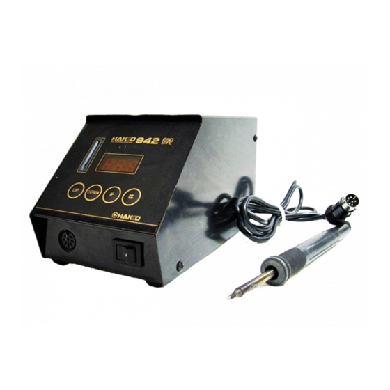
- Page 1 High - output, temperature controlled soldering station...
-
Page 2: Packing List
1. PACKING LIST Hakko 942 soldering station ......1 Tip tray ............1 Hakko 912 soldering iron ........ 1 Cleaning sponge ..........1 Power cord ............1 Instruction manual .......... 1 Control card ............ 1 Card chain ............1 Heat resistant pad ........... 1 Tips (not included) Iron holder ............ -
Page 3: Warnings, Cautions, Notes And Examples
To prevent accidents or damage to the Hakko 942, be sure to observe the following: Do not use the Hakko 942 for applications other than soldering. Do not allow the Hakko 942 to become wet, or use it when hands are wet. Do not modify the Hakko 942. -
Page 4: Part Names
4. PART NAMES Control card Card chain Receptacle Station Fuse Power switch Power receptacle Cleaning sponge Hakko 912 Tip (not included) Soldering iron Iron holder Tip tray Power cord Heat resistant pad... -
Page 5: Initial Setup
5. INITIAL SETUP A. Iron holder 1. Adjust the height of the iron holder to suit, as follows: i. Loosen the adjusting screws. ii. Set the iron holder to the desired height. iii. Tighten the screws. 2. Put the small cleaning sponge in one of the four holes in the iron holder base. -
Page 6: Soldering Station
2. Set the iron in the iron holder . 3. Plug the power cord into a grounded wall socket. The Hakko 942 is protected against electrostatic discharge and must be grounded for full efficiency . -
Page 7: Operation
CAUTION: CAUTION: Place the iron in the iron holder when not in use. The Hakko 942 is preset at 350 °C. at the factory . Check the temperature setting by pressing the button. The set temperature will be displayed for two seconds. -
Page 8: Factory Settings
Factory settings The Hakko 942 comes from the factory with the following values preset: Temperature scale Celsius Auto power shutoff disabled Low temperature alarm setting 150°C Resetting the supervisor/ operator control setting Set temperature 350°C Control card Each Hakko 942 comes with a small card, which inserts in the control slot in the front of the unit. -
Page 9: Replacing The Tip
3. Entering the tens digit • Press the button to set the desired figure. Any value from 0 to 9 can Press the button. be selected. When the desired figure is displayed, press the button to enter . The units digit will begin to flash. 4. -
Page 10: Entering Tip Offset Values
The Hakko 942 has the ability to electronically compensate for the variations due to tip temperature offset. When a soldering tip is changed, the proper offset temperature value should be programmed into the 942. -
Page 11: Parameter Settings
8. PARAMETER SETTINGS Entering the parameters The Hakko 942 has the following four parameters: 1) °C or °F temperature display selection 2) Auto power shutoff 3) Low-temperature alarm tolerance setting 4) Resetting the supervisor/operator control setting Once the station enters parameter mode, set the parameters in the order shown below. - Page 12 • If you enter a value exceeding the allowable buzzer will stop. The value is stored in the range shown to the left, you will be brought Hakko 942 as described in the example below: back to entering a value in the hundreds digit. EXAMPLE: If this occurs, re-enter a correct value.
-
Page 13: Tip Maintenance
Always clean the soldering tip before use, to remove any residual solder or flux adhering to it. Use a clean and moist cleaning sponge (provided with the Hakko 942) or the Hakko 599 tip cleaner . Contaminants on the tip have many deleterious effects, including reduced heat conductivity , which contribute to poor soldering performance. -
Page 14: Checking Procedure
Checking Procedure WARNING: Unless otherwise directed, carry out these procedures with the power switch OFF and the power UNPLUGGED. Check for a broken heater or 1. Check for a broken heater or sensor sensor Measure the resistance across this position. Verify the electrical integrity of the heater and sensor . -
Page 15: Error Messages
Low-temperature alarm tolerance Soldering iron error When the Hakko 909 or Hakko 91 1 soldering iron is connected to the Hakko 942 station, will be displayed. NOTE: Only the Hakko 912 iron is to be used with the Hakko 942 station. -
Page 16: Troubleshooting Guide
11. TROUBLE SHOOTING GUIDE WARNING: • Before checking the inside of the Hakko 942 or replacing parts, be sure to disconnect the power plug. Failure to do so may result in electric shock. The unit does not CHECK : Is the power cord and/or the connection plug dis-... -
Page 17: Parts List
Plain washer) (M4 × 8) (4) (M4 × 6) (2) Pan head screw (w/Spring washer) (M3 × 6) (3) Pan head screw (M4 × 55) 942 Station Item No. Part No. Name Description Item No. Part No. Name Description B2579... - Page 18 • 912 Iron Item No. Part No. Name Description 912-01 Hakko 912 24V-70W • 912 Parts Item No. Part No. Name Description B2576 Handle assembly With connecting cord B2577 O-ring spacer B2578 O-ring (ø5.6) B2575 Nipple With handle cover, O-ring (ø5.6) See page 18 B2665 Heat resistant pad...
-
Page 19: Tip Styles
13. TIP STYLES Unit: mm T2-B Shape-B 23.7 113.7 T2-1C Shape-1C T2-4C Shape-4C T2-2B Shape-2B T2-4CF Shape-4C Cut-Surface Pre-tinned 10.5 T2-1BC Shape-1BC T2-2BC Shape-2BC T2-3BC Shape-3BC T2-1BCF Shape-1BC Cut-Surface Pre-tinned T2-2BCF Shape-2BC Cut-Surface Pre-tinned T2-3BCF Shape-3BC Cut-Surface Pre-tinned T2-12D Shape-1.2D T2-08D Shape-0.8D T2-16D Shape-1.6D T2-24D Shape-2.4D... -
Page 20: Wiring Diagram
14. WIRING DIAGRAM Power switch Power receptacle P.W.B./Power supply Brown Blue/220-240V Black White/100-120V Grounding plate P.W.B./Temperature control 1 2 3 4 5 Transformer Connector board HEAD OFFICE PENANG BRANCH 4-5, SHIOKUSA 2-CHOME, NANIWA-KU, OSAKA, 556-0024 JAPAN 19,LORONG IKS JURU 3,TAMAN PERINDUSTRIAN RINGAN JURU, TEL:+81-6-6561-3225 FAX:+81-6-6561-8466 14100 SEBERANG PERAI TENGAH,PENANG,MALAYSIA.
Need help?
Do you have a question about the 942 and is the answer not in the manual?
Questions and answers