Advertisement
®
Instruction Manual
Thank you for purchasing the HAKKO 936 Soldering Station.
Please read this manual before operating the HAKKO 936.
Store the manual in a safe, easily accessible place for future reference.
SOLDERING STATION
Table of Contents
Packing List/ Specifications ........................1
Precautions.............................................2
Names of Parts .......................................3
Setting up & Operating the HAKKO 936......3 4
Calibrating the Iron Temperature............5
Tips ......................................................6
Troubleshooting Guide ..............................7
heating element and cord assembly......8 9
Station / Iron Holder...........................10
Iron................................................11
Wiring Diagram.......................................11
Advertisement
Table of Contents

Related Manuals for Hakko Electronics 936


Summary of Contents for Hakko Electronics 936
-
Page 1: Table Of Contents
® SOLDERING STATION Instruction Manual Thank you for purchasing the HAKKO 936 Soldering Station. Please read this manual before operating the HAKKO 936. Store the manual in a safe, easily accessible place for future reference. Table of Contents Packing List/ Specifications ……………………1 Precautions………………………………………2... - Page 2 Packing List Please check the contents of the HAKKO 936 package and confirm that all the items listed below are included. HAKKO 936 Station …………………………………1 Soldering Iron (HAKKO 900 (S), 907 or 908) ……1 HAKKO Iron Holder (With Cleaning Sponge) ……1 Hex Wrench (1.5 mm,0.059 in.)……………………1...
-
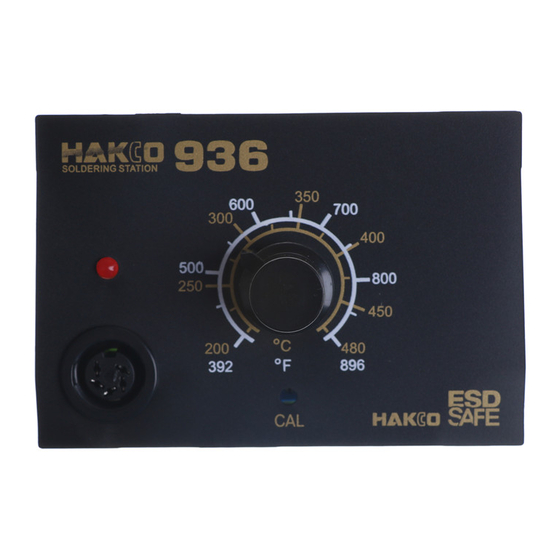
Page 4: Names Of Parts
CAL Pot Plug/Calibrator Power Switch Hex Wrench Setting up & Operating the HAKKO 936 CAUTION:The sponge is compressed. It will swell when moistened with water. Before using the unit, dampen the sponge with the water and squeeze it dry. Failure to do so may result in damage to the soldering tip. - Page 5 C. Set the Temperature 1. Set the temperature control knob to the desired temperature. 2. Lock the knob. The HAKKO 936 station is equipped with a temperature control knob lock. After setting the desired temperature, tighten the hex nut on the underside of the knob mount using the supplied hex wrench.
-
Page 6: Tip Care And Use
Tip Care and Use •Tip Temperature High soldering temperatures can degrade the tip. Use the lowest possible soldering temperature. The excellent thermal recovery characteristics ensure efficient and effective soldering even at low temperatures. This also protects the soldered items from thermal damage. •Cleaning Clean the tip regularly with a cleaning sponge, as oxides and carbides from the solder and flux can form impurities on the tip. -
Page 7: Tips
Tips The tip temperature will vary according to the shape of the tip. The preferred method of adjustment uses a tip thermometer. (See “Calibrating the Iron Temperature” on page 5.) A less accurate method involves adjusting the temperature control knob according to the adjustment value for each tip. Example : When using a 900M-T-H tip at 400 C (750 F), the difference between this tip and a 900M-T-B is -20 C (-36 F). -
Page 8: Troubleshooting Guide
Troubleshooting Guide WARNING : * Disconnect the power plug before servicing. Failure to do so may result in electric shock. * If the power cord is damaged, it must be replaced by the manufacturer, its service agent or similarity qualified person in order to avoid personal injury or damage to the unit. -
Page 9: Checking For Breakage Of The Heating Element And Cord Assembly
Checking for breakage of the heating element and cord assembly Disconnect the plug and measure a Between pins 4&5 (Heating Element) 2.5 - 3.5 (Normal) the resistance value between the b Between pins 1&2 (Sensor) 43 - 58 (Normal) connecting plug pins as follows. c Between pin 3&Tip Under 2 If the values of 'a' and 'b' are outside... -
Page 11: Parts List
Parts List (Station/Iron Holder) Note:Spare or repair parts do not include mounting screws, if they are not listed on the description. Screws must be ordered separately. Binding Head Tapping Screw (Fluted Point) M 3.5 ~50 (4) M 3.5 ~40 (4) for No.B2228 Hexagon Socket Head Cap Screw Transformer M 2 ~8 (1) -
Page 12: Iron
Parts List (Iron) 900S Item No. Part No. Part Name Description 900S-006 900S-006S E.S.D. Soldering Tip See. P.6 A1322 Heating Element Old part No.900S-H 900S-101 Terminal Board w/Cord Stopper 900S-001 Handle w/Handle Cover 900S-001S Handle w/Handle Cover, E.S.D. 900S-034 Handle Cover 900S-034S Handle Cover E.S.D.
Need help?
Do you have a question about the 936 and is the answer not in the manual?
Questions and answers