
Related Manuals for Vaderstad Rapid RDA 400S

Summary of Contents for Vaderstad Rapid RDA 400S
- Page 1 Rapid series RDA 400S Maunfacturing No. 14800- Instructions 900285-en 27.06.2011 ver. 2 Original instructions...
- Page 2 27.06.2011 ver. 2...
- Page 3 RDA 400S...
-
Page 5: Table Of Contents
RDA 400S Safety regulations Before using the drill ................9 Warning decals ................. 10 Location of warning decals on the machine ........... 11 Other safety precautions ..............12 Data plates ..................13 Moving the machine when not hitched to a tractor ......... 15 Installation instructions Installation of the Control Station on the tractor ........ - Page 6 Advice on seeding and driving instructions Sowing depth ..................84 Checking the seed feed ..............85 Sowing headlands ................86 Engaging the drill ................86 Intermediate packer ................87 Tramlining ..................88 Bout markers ..................88 Obstructions ..................88 Turning with Low lift ................88 Maintenance and service General maintenance .................
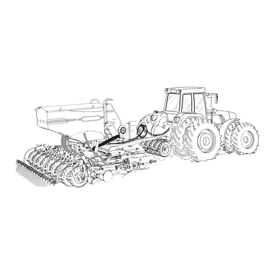
- Page 7 RDA 400S INTRODUCTION Väderstad Rapid A 400 S is a high-capacity cultivation drill. The Rapid drills can be used under a large variety of conditions, from "direct drilling" to sowing straight after the plough. This versatility is made possible by the drill's coulter system design and its unique depth control system, amongst other features.
- Page 8 EC DECLARATION OF CONFORMITY FOR THE MACHINE in accordance with the EU Machinery Directive 2006/42/EC Väderstad-Verken AB, P.O. Box 85, SE-590 21 Väderstad, SWEDEN hereby confirms that the drilling machines hereunder have been manufactured in accord- ance with the Council Directives 2006/42/EC and 2004/108/EC. The above declaration covers the following machines: RDA 400S, manufacturing no.
-
Page 9: Safety Regulations
RDA 400S Safety regulations Before using the drill Figure 1.1 ! Always pay extra attention to paragraphs or figures bearing the following symbol: ! Learn to handle the drill correctly and with care. The drill can be dangerous in inexperienced or careless hands. -
Page 10: Warning Decals
Safety regulations Warning decals Figure 1.2 Read the instructions carefully and make sure you understand them. Always make sure that the entire working area and folding area of the seed drill are unobstruct- ed. Never walk under a suspended section. Always check that the automatic catches have en- gaged in connection with transport and parking. -
Page 11: Location Of Warning Decals On The Machine
RDA 400S Location of warning decals on the machine G,H,I,K A,B,D,L Figure 1.3 27.06.2011 ver.2... -
Page 12: Other Safety Precautions
Safety regulations Other safety precautions ! Observe the greatest caution when transporting the seed drill on a public road. If the machine has a full hopper, note that the towed weight is considerable and that the view to the rear is greatly restricted. -
Page 13: Data Plates
RDA 400S Data plates ! The machine is equipped with either a combination of signs 1.5.1, Serial number plate, and 1.5.2, CE plate, or 1.5.3, Machine label. 1.5.1 Serial number plate Figure 1.4 Type number Manufacturing number. Always state the manufacturer number for your machine when order- ing spare parts and in case of warranty claims. - Page 14 Safety regulations 1.5.3 Machine label Figure 1.6 Machine type Manufacturing serial number (Always state the serial number of your machine when ordering spare parts and in case of serv- icing or warranty claims.) Year of manufacture Working width Transport width Tare weight of the basic machine Maximum total weight Maximum permitted payload...
-
Page 15: Moving The Machine When Not Hitched To A Tractor
RDA 400S Moving the machine when not hitched to a tractor NOTE! If the machine must be moved when not hitched to a tractor,it must be transported on a ma- chine trailer or lorry flatbed! The machine must be rolled onto and off the transport vehicle using a tractor. Lifting with a crane is prohibited! 1 Set the machine to the transport position;... - Page 16 Safety regulations 27.06.2011 ver. 2...
-
Page 17: Installation Instructions
RDA 400S Installation instructions Installation of the Control Station on the tractor Figure 2.1 Figure 2.2 1 Be sure to install the control box securely in the tractor cab. Place the control box within the field of vision while looking in the travelling direction. Install the bracket as shown in the il- lustration. -
Page 18: Instructions And Settings
Instructions and settings Instructions and settings All basic adjustments must be carried out with the Rapid drill on a level surface, with the NOTE! wing sections lowered and with the drill hitched to a tractor. Tractor Figure 3.1 Figure 3.2 3.1.1 Tyre equipment and weights To reduce soil compaction and to increase the pull, the tractor should be fitted with very good... -
Page 19: Hitching And Unhitching The Seed Drill Without An Intermediate Packer
RDA 400S Hitching and unhitching the seed drill without an inter- mediate packer 3.2.1 Hitching Figure 3.3 1 Connect the drill to the tractor hitch device. 2 Raise and secure the machine parking stay. 3 Fold the hose holder forward and connect the hydraulic hoses and electrical cabling, see also ”3.4 Connecting the hydraulic hoses and electrical cables”... - Page 20 Instructions and settings 3.2.2 Unhitching Figure 3.4 ! Unhitching and parking must always take place on a level and solid surface. 1 Lower and secure the machine parking support. 2 Be sure to adjust the master ram stopper and the parking stay in such a way that the drill rests on the wheels, discs and its stay when parked.
-
Page 21: Hitching And Unhitching The Seed Drill With An Intermediate Packer
RDA 400S Hitching and unhitching the seed drill with an interme- diate packer 3.3.1 Hitching Figure 3.6 Figure 3.7 1 Connect the drill to the tractor lifting arms. The Class 3 screw taps must be used. Figure 3.8 2 Fold the hose holder forward and connect the hydraulic hoses and electrical cabling, see also ”3.4 Connecting the hydraulic hoses and electrical cables”... -
Page 22: Connecting The Hydraulic Hoses And Electrical Cables
Instructions and settings 3.3.2 Unhitching Figure 3.9 1 Park the machine on a firm surface. 2 Depressurize the hydraulic system. 3 Disconnect the drill from the tractor lifting arms. 4 Disconnect the hydraulic hoses and electrical cables. Fold back and secure the hose holders in the upright position. - Page 23 RDA 400S 3.4.2 Hose connections to the fan and delivery system Figure 3.10 Figure 3.11 1 Connect the two thin hoses to a two-way hydraulic connector designed for continuous opera- tion of a hydraulic motor. If available, use a priority connector. The thicker hose of these two hoses is the pressure hose to the hydraulic motor, while the thinner is the oil leakage hose.
-
Page 24: Hose Length And Hose Holder Adjustment
Instructions and settings Hose length and hose holder adjustment Figure 3.13 The seed drill is equipped with a folding hose holder. The holder can be fitted in different positions along the drawbar, and it should be located as close to the tractor as possible to work best. The hose holder should also, in most cases, be pulled out to its full length. -
Page 25: Wheel Retraction Mechanism (Only Machines With The Hydraulic Depth Adjustment Option)
RDA 400S Wheel retraction mechanism (only machines with the hydraulic depth adjustment option) Figure 3.14 Risk of crushing in the spring-loaded wheel retraction mechanism. Always use suitable NOTE! tools when operating the locking devices, e.g. using the supplied key (C)! Also see ”3.7 Changing between transport position and working position”... -
Page 26: Changing Between Transport Position And Working Position
Instructions and settings Changing between transport position and working position 3.7.1 Changing to working position Figure 3.15 Lift the seed drill to its top position. Folding the wing sections in and out must always be car- ried out with the seed drill fully raised. Also check that the tool bar is fully raised before folding out. - Page 27 RDA 400S Figure 3.19 Figure 3.20 Keep the hydraulic lever on the tractor in the lowering position ( "Floating" position Note! must not be used) until the ram ("folding ram") is fully refilled, locking the wing sections in the unfolded position. See “Figure 3.19”. Figure 3.21 Always drive forwards when the seed drill is lowered to its working position, to prevent the seed coulters becoming clogged.
-
Page 28: Horizontal Alignment
Instructions and settings Horizontal alignment Figure 3.22 27.06.2011 ver. 2... - Page 29 RDA 400S The longitudinal inclination of the drill can be adjusted using the push rod (A) with the machine resting on solid, level ground. When correctly adjusted, the front and rear row of drill discs should reach the ground at the same time when the machine is lowered. Loosen the lock nut (B), adjust to the desired position, and then tighten the lock nut.
-
Page 30: Mechanical Adjustment Of Sowing Depth
Instructions and settings Mechanical adjustment of sowing depth Figure 3.24 The drilling depth of the centre section is set using the stop bolt (A). The drilling depth of the side sections is adjusted with the cranks (B). The scale indications do not constitute absolute values of the drilling depth in centimetres but serve as an index only. -
Page 31: Hydraulic Adjustment Of Sowing Depth (Option 15582-)
RDA 400S 3.10 Hydraulic adjustment of sowing depth (option 15582-) 3.10.1 Adjusting the master and slave system Figure 3.25 The sowing depth of the drill is controlled by three hydraulic rams connected in series in a so- called master and slave system. Before using the drill for the first time, the rams must be bled and their position zeroed in relation to each other thus: Raise the drill to its topmost position so that all hydraulic rams are fully extended. - Page 32 Instructions and settings 3.10.2 Drilling depth setting using the Interactive DepthControl function (IDC) The drill is equipped with the Interactive Depth Control feature (IDC), which enables fine adjust- ment of the drilling depth from the tractor cab while driving. The drilling depth is set according to ”3.10.2 Drilling depth setting using the Interactive DepthControl function (IDC)”...
- Page 33 RDA 400S The function is kept engaged automatically for the time duration selected in the calibration menu (3 - 60 seconds) or until the button is depressed once again. When the Interactive Depth Control function is not engaged, the symbol is displayed to- gether with the current scale value.
-
Page 34: Adjusting The Wing Sections
Instructions and settings 3.11 Adjusting the wing sections Figure 3.28 A hydraulic lock is used to lock the extending/retracting ram automatically in the extended posi- tion, to keep the machine "rigid". This is to ensure even performance across the entire operating width. -
Page 35: Adjusting The Changeover Valve
RDA 400S 3.12 Adjusting the changeover valve Figure 3.29 The valve is usually pre-set on delivery from the factory. The reverse switch (A) activates/deacti- vates the control system for lowering of the wing sections. When the drill is lowered in working mode, one of the double-acting hydraulic take-offs of the tractor is linked to the tool bar only. -
Page 36: Adjustment Of The Pre-Implements
Instructions and settings 3.13 Adjustment of the pre-implements 3.13.1 System Crossboard, System Agrilla Figure 3.30 The pre-implements are normally preadjusted at the factory. Similar to the lifting system, the pre-implements are also connected to a master and slave system. Prior to adjusting the pre-implements, bleed and reset the hydraulic system in the same was as the lifting system. - Page 37 RDA 400S 3.13.2 System Disc Figure 3.31 The System Disc pre-implement has normally been reset at the factory. Similar to the lifting system, the pre-implement is connected to a master and slave system. Prior to adjusting the pre-implement, bleed and reset its hydraulic system in the same was as the lifting system.
-
Page 38: Adjusting The Following Harrow
Instructions and settings 3.14 Adjusting the following harrow Figure 3.32 1 Select a suitable work angle from row of holes B. 2 The work pressure of the following harrow is adjusted using the adjusting screw (A). Depend- ing on the work pressure set on the following harrow, the cotter (C) should be positioned be- tween the trailing edge and centre of the oblong groove (D). -
Page 39: Adjusting Low Lift Height
RDA 400S 3.15 Adjusting Low lift height Figure 3.34 Low lift height can be adjusted by moving the reed switch up or down in its holder using the wing bolt (A) which is tightened using the wing nut (B). This setting must be exact. The Low lift height must not be set either too high or too low. NOTE! Too high a setting reduces the pressure on the following harrow in the headlands (unless this is required). -
Page 40: Adjusting The Seed Coulters
Instructions and settings 3.17 Adjusting the seed coulters NOTE! Before commencing any work under the drill, be sure to secure it in the raised position. See ”3.16 Locking the lifting rams during service” on page 39. 3.17.1 Installation height Figure 3.37 Figure 3.38 To ensure a satisfactory sowing result, it is important that the seed coulters are correctly installed on the drill. - Page 41 RDA 400S 3.17.2 Tightening nuts Figure 3.40 Figure 3.41 The seed coulters are spring-mounted on two bolts and the soft washers press the seed coulters closer to the discs as the nuts are tightened. Do not tighten the nuts more than the coulters can be easily tilted with one hand.
-
Page 42: Scraper
Instructions and settings 3.18 Scraper C=5 mm Figure 3.42 The scraper default settings are shown in the figure. The scraper position can be adjusted in two places. If the setting (A) is insufficient, the holder (B) can be adjusted lengthwise. NOTE! The distance (C) between the scraper blade and the tyre must not be less than 5 mm. -
Page 43: Bout Marker Adjustment
RDA 400S 3.19 Bout marker adjustment RDA 400: 4,0 m Figure 3.43 Adjust the bout markers as shown in “Figure 3.43”. This adjustment is approximate. To avoid dou- ble-seeding or non-seeding, which may occur if the driver sits at an angle in the tractor, a follow- up check should be done in the field. -
Page 44: Track Eradicators, System Disc
Instructions and settings 3.21 Track eradicators, System Disc Figure 3.45 Drills equipped with the System Disc pre-implement have three reversible discs on each side. If required, these discs can be setter to a deeper depth than the other discs to enable eradication of the tractor's wheel tracks. -
Page 45: Setting The Radar
RDA 400S 3.23 Setting the radar 35° Figure 3.47 The angle of the radar unit must be adjusted. The angle must be 35° +/- 1° in relation to the soil surface. The angle of the radar is optimal when the surface (A) is parallel to the soil surface. Loos- en the screws (B) and adjust the bracket along the oblong hole. -
Page 46: Adjusting The Air-Flow
Instructions and settings 3.24 Adjusting the air-flow 3.24.1 Hydraulic fan "Fenix" The air volume is adjusted using the fan speed. The fan speed can be adjusted in various ways, depending on the tractor on which it is mounted: The fan is controlled using the tractor’s flow valve. A flow valve is available on most tractors with a constant pressure hydraulic system. -
Page 47: Seed Box Setting
RDA 400S 3.25 Seed box setting Figure 3.52 If the drill is fitted with hydraulic feed output, then the output amount is determined by the rota- tional speed of the seed box and its setting. The seed box is set according to the sowing table col- umns for hydraulic feed output. -
Page 48: Calibration
Instructions and settings 3.26 Calibration 1 Set the seed box. See ”3.25 Seed box setting” on page 47. Figure 3.53 2 Use the enclosed bag for calibration. Prior to calibration, reset the scale with the bag empty. Push the bag into the seed box from below through the spring-loaded door. Figure 3.54 3 Switch off the hydraulic fan by turning the lever to position B. - Page 49 RDA 400S 5 To access the calibration menu, depress the button on the Control Station. (Alternatively, the calibration menu can be called up by simultaneously depressing the buttons on the Control Station.) Figure 3.55 ! Use the dial to select a row in the menu, mark the row and press to confirm.
- Page 50 Instructions and settings Figure 3.57 10 Keep on the Control Station or the remote control depressed until a suitable seed amount has been filled into the bag. Pulses from the seed boxes are counted up in menu row 3. Figure 3.58 11 Weigh the content of the bag.
- Page 51 RDA 400S 13 Select EXIT and press Figure 3.59 14 Set the hydraulic fan valve to position A. 3.26.1 Decreasing the scale value of the seed box when the seed hopper is full The scale value can be reduced in steps of 5-10 scale divisions even after the seed hopper has been filled.
- Page 52 Instructions and settings 3.26.2 Scale Hold 2.24 Figure 3.60 Figure 3.61 Weigh calibrations as follows: 1 Press Start/Reset. 2 Hang the empty calibration bag on the scale hook. 3 The weight of the bag is shown. Wait until "Hold" is displayed. 4 Press Start/Reset.
-
Page 53: Prior To Filling The Hopper
RDA 400S 3.27 Prior to filling the hopper Check that: ! the machine is empty, clean and dry. ! the seed housing is set as shown in the sowing table. ! the emptying hatch is closed. 3.27.1 Filling from bulk sacks Figure 3.62 NOTE! Pay attention to safety. -
Page 54: Emptying The Seed Hopper
Instructions and settings 3.27.2 Filling from small sacks Pay attention to safety. Do not walk under a suspended load! Make sure there is nobody on NOTE! the drill when feeding the seed. Make sure there is nobody on the hopper. Avoid contact with and inhalation of seed disinfectant. -
Page 55: Operation Test
RDA 400S 3.29 Operation test Figure 3.66 To check the actual output, a running test can be performed. This is recommended especially when the seed drill is new or is used on a different surface to the previous one. When carrying out measurement, drive a distance (L) of 25 m with the RDA 400 S. NOTE! The fan should be turned off. -
Page 56: Control Station
Instructions and settings 3.30 Control station Figure 3.67 27.06.2011 ver. 2... - Page 57 RDA 400S 3.30.1 Functional description 1 Main switch - Activation of the Control Station when starting. - Master stop (all feeding stops and "STOP" is displayed on the 3rd and 4th row) Calibration 4 Not used 5 LCD display 6 Tramlining indicator lamps Off = No tramlining Green light = Tramlining and correct operation Red light = Incorrect tramlining...
- Page 58 Instructions and settings Figure 3.68 27.06.2011 ver. 2...
- Page 59 RDA 400S 21 Manual start. By keeping the button pressed, seed is fed out without the machine advancing. This is used e.g. when starting in a corner of the field or when verifying the feed output. Use the programming menu for presetting the seed output amount in relation to the drive speed. 22 - Electric adjustment of sown seed amount, increase (in max.
- Page 60 Instructions and settings Low-lift/Full lift Use push-button to switch between low-lift and full lift. The indicator lamps next to the button show which function has been engaged. Use low-lift when drilling. This prevents the ma- chine from being raised too much, while allowing proper operation of the following harrow in the headland.
- Page 61 RDA 400S Shut-off of seed feeding Feeding can be shut off by depressing the button (18) on the left side. The indicator lamp shows the seed feeding has been shut off. Electric adjustment of sown seed amount (only applies for hydraulic feed output) The default value and percentage change are recorded in the calibration menu.
- Page 62 Instructions and settings Information Press to access the information menu. Advance by turning the knob. If an alarm simulta- neously appear on the Control Station, the alarm texts are shown first. The information menu shows: seed trip meter (kg), , trip area meter (ha), , trip seasonal area meter (ha), , trip total area meter (ha),...
- Page 63 RDA 400S 3.30.3 Programming The Control Station has been preset at the Väderstad factory depending on the type and size of the machine it is supplied with. The Control Station settings need to be reentered after replacement or a reset. It is also possible to use the settings to adjust e.g., alarm delays, area metering, etc.
- Page 64 Instructions and settings Number of radar pulses per meter of driven distance. Default setting 99/m. Number of pulses per wheel rotation. Default setting: 1. Drive wheel circumference Default setting 240 cm. AUTO . Automatic calibration. Measure a given distance (at least 100 m). Press at the starting point.
- Page 65 RDA 400S Wing locking, Yes/No. Only “No” is used for the RDA 400 S. It is possible to enter user-specific information, e.g., a name. Use the dial to enter char- acters and digits, and advance using Setting the display contrast. Use the dial to set the contrast between 0% (lighter) and 100% (darker).
- Page 66 Väderstad-verken AB. Proceed as follows: 1 Log on to the Väderstad home page at http://www.vaderstad.com. 2 Click on "Downloads" to download the installation programme onto your computer. 3 Run the new software application while following the on-screen instructions. New files are cre- ated and/or updated.
-
Page 67: Interactive Depth Control Function, Idc (Option 15582-)
RDA 400S 3.31 Interactive Depth Control function, IDC (option 15582-) ! In order to use the Interactive Depth Control function, the Control Station must be loaded with firmware version 210004 or later. If “Yes” is selected in the programming menu , see ”3.30.3 Programming”... - Page 68 Instructions and settings 3.31.2 Calibration menu Figure 3.72 6 Use this to set the time duration for keeping the Interactive Depth Control function engaged when the button on the Control Station has been depressed (3 to 60 seconds). 7 An ultrasonic transmitter has been installed on the lifting ram. It measures the so-called bit val- ue to determine the exact position of the lifting ram.
- Page 69 RDA 400S 3.31.3 Drilling depth setting using the Interactive Depth Control function Figure 3.73 Figure 3.74 To engage the Interactive Depth Control function, depress the button. When this function is engaged, the indicator lamp in the button blinks, the alarm indicator blinks and a buzzer sounds.
- Page 70 Instructions and settings 3.31.4 Ultrasonic transmitter Figure 3.75 The distance (A) between the ultrasonic transmitter and the plate at maximum raised position should be max. 500 mm. If work needs to be performed close to the ultrasonic transmitter and there is a risk that the ultra- sonic ray may be interrupted, the Control Station must be blocked beforehand with the (“STOP”) and buttons.
-
Page 71: Tramlining
RDA 400S 3.32 Tramlining 3.32.1 Tramlining flaps Figure 3.77 Figure 3.78 Tramlining is carried out by the spring loaded tramlining flaps (A) which are integrated into the outlets of the seed distributor heads in the seed hopper. In the activated position (Position 1) the flaps are raised into place to close the outlet while opening a trap to allow seed to return to the hopper. - Page 72 Instructions and settings 3.32.2 Tramline options The RDA 400 S model is supplied with equipment for centre marking installed. Table 3.3 Tramlining options RDA 400 S centre marking 8, 12, 16, 20, 24 metre RDA 400 S side marking 16, 24 and 32 metre The drill is supplied having two or three row shutoff.
- Page 73 RDA 400S Table 3.4 The most common tramlining systems (centre marking) Machine Tramlining Tramlining Start Remarks width programme value RDA 400 S 12 m RDA 400 S 16 m First bout half overlapped by the second bout.* RDA 400 S 20 m RDA 400 S 24 m...
- Page 74 Instructions and settings 3.32.3 Adjusting track width Figure 3.80 The Rapid drill is usually supplied with the row shutoff and track width specified by the customer. However, it is possible to change these if necessary: ! A different track width can be obtained by shifting the feed hoses to the seed coulters. Example: A track width of 1.75 m can be increased to 2.0 m by moving the front left and rear right one step outwards.
-
Page 75: Adjusting The Pre-Emergence Bout Marker
RDA 400S 3.33 Adjusting the pre-emergence bout marker Figure 3.82 The pre-emergence bout marker should be adjusted to the tramlining width. Move the tines (A) laterally on the frame. The angle of the bout marker discs can be adjusted by turnings the shafts (B) in their holders. -
Page 76: Hydraulic Brakes (Accessories)
Instructions and settings 3.34 Hydraulic brakes (accessories) 3.34.1 General The RDA 400 can be fitted with hydraulic brakes. The system also has an emergency brake that is applied if the machine becomes unhitched from the tractor. The emergency brake system con- sists of an accumulator, a valve and a wire that is connected to the tractor. - Page 77 RDA 400S 3.34.3 Parking Figure 3.84 Always park the drill on a stable and level surface. Secure the drill with the brake pads (B). 27.06.2011 ver.2...
-
Page 78: Maintenance Of Hydraulic Brake System
Instructions and settings 3.35 Maintenance of hydraulic brake system 3.35.1 Maintenance at the start of the season Figure 3.85 1 Adjust the brake pads. Screw the adjustment screw (A) clockwise while rotating the wheels slowly. Turn the adjustment screw until you feel resistance in the wheels as they rotate. This means that the brake pads are in gentle contact with the brake drums. -
Page 79: Pneumatic Brakes (Accessories)
RDA 400S 3.36 Pneumatic brakes (accessories) The RDA 400 can be fitted with pneumatic brakes. 3.36.1 Use while driving 1 Connect the lines to the tractor’s couplings. ! The compressed air line has a red mounting and must be connected to the red coupling. ! The control line has a yellow mounting and must be connected to the yellow coupling. - Page 80 Instructions and settings 3.36.2 Activation of parking brake Figure 3.87 In order to activate the parking brake, proceed as follows: 1 Connect the compressed air lines to the tractor’s couplings as described above. 2 Activate the tractor’s parking brake. 3 Close the needle valve (B) on the main ram. This closes the hydraulic circuit between the main ram and the wheel cylinders.
- Page 81 RDA 400S 3.36.3 Daily maintenance Figure 3.88 Figure 3.89 1 Drain off the condensation water from the compressed air container. Open the discharge valve (C) on the underside of the container. 2 Check the oil level in the container (D) on the main ram. The level should be between the Max and Min markings on the container.
-
Page 82: Maintenance Of Pneumatic Brake System
Instructions and settings 3.37 Maintenance of pneumatic brake system 3.37.1 Maintenance at the start of the season Figure 3.90 1 Adjust the brake pads. Screw the adjustment screw (A) clockwise while rotating the wheels slowly. Turn the adjustment screw until you feel resistance in the wheels as they rotate. This means that the brake pads are in gentle contact with the brake drums. - Page 83 RDA 400S 3.37.2 Bleeding the brake system Figure 3.91 Following maintenance or other work on the hydraulic system, the brake system must be bled be- fore use. 1 Top up the container with oil to the Max marking. 2 Connect a brake bleeding tool (max. 1 bar) to the main ram connect the compressed air line and the control line to the tractor and apply the brakes connect the compressed air line and the control line to an external compressed air source (max.
-
Page 84: Advice On Seeding And Driving Instructions
Advice on seeding and driving instructions Advice on seeding and driving instructions Sowing depth Figure 4.1 See ”3.9 Mechanical adjustment of sowing depth” on page 30, ”3.10 Hydraulic adjustment of sowing depth (option 15582-)” on page 31 and ”3.11 Adjusting the wing sections” on page 34. The most important task for the Rapid operator is to carefully and continually check the sowing depth. -
Page 85: Checking The Seed Feed
RDA 400S Checking the seed feed Figure 4.2 The seed feed should be checked at the same time as the sowing depth, i.e. after every 4 hectares or once an hour. In connection with output verification, check that the machine appear to be outputing the same amount from each coulter. -
Page 86: Sowing Headlands
Advice on seeding and driving instructions Sowing headlands Figure 4.3 In dry and fine conditions, the headlands should be sown first. In wet conditions or on soils sus- ceptible to compaction, higher yields can be obtained if the headlands are sown last. The headlands can be marked out by finishing off the last tillage operation before sowing (e.g. -
Page 87: Intermediate Packer
RDA 400S Intermediate packer Figure 4.5 Figure 4.6 The intermediate packer should be in the lowered position when pulled in the furrow as well as on the headland. Always lift the intermediate packer when reversing the seed drill. If the packer is not lifted, the wheel undercarriage and the wheels themselves could be damaged. -
Page 88: Tramlining
Advice on seeding and driving instructions Tramlining The preparation of tramlines and setting of the Control Station are described in ”3.30.2 Func- tions” on page 59 and ”3.32.2 Tramline options” on page 72. During sowing, the most important thing to remember about tramlining is to shut off Autostep before doing anything other than normal sowing or turning in headlands between bouts. - Page 89 RDA 400S 27.06.2011 ver.2...
-
Page 90: Maintenance And Service
Maintenance and service Maintenance and service Figure 5.1 Figure 5.2 Figure 5.3 During all work under the drill or where there is a danger of crushing, the drill must be NOTE! completely and securely supported. Secure the drill on trestles or stands and lock all lifting rams with their yellow locking devices. - Page 91 RDA 400S Figure 5.4 27.06.2011 ver.2...
-
Page 92: General Maintenance
Maintenance and service General maintenance Figure 5.5 A machine is only as good as the service it receives! Before starting work, check that all nuts and screws are tightened. During the season, check the tightness of nuts and screws regularly, as well as the wear on linkages and the hydraulic ram mountings. -
Page 93: Inspecting The Drill's Towing Eyelet
RDA 400S Inspecting the drill's towing eyelet Max +2.5 mm Figure 5.6 5.2.1 Alternative drawbar eyes 50 mm drawbar eye diameter (standard). 40 mm drawbar eye diameter (standard). Ball hitch, 80 mm diameter. Swivel drawbar eye, 57 mm diameter. 5.2.2 Re-tightening of screw connections The screw connections (E) of the drawbar eye must be re-tightened at regular intervals. -
Page 94: Seed Feed Housing And Rape Brush
Maintenance and service Seed feed housing and rape brush Figure 5.7 Figure 5.8 The inside of the seed feed housing must be cleaned out regularly and frequent checks must be made for signs of wear on plastic and rubber components. It is specially important to ensure that seed additive deposits do not build up in the scoops, reducing their volume. -
Page 95: Cleaning
RDA 400S Cleaning Figure 5.10 Figure 5.11 Figure 5.12 At regular intervals and at the end of the season, check that there is no seed or packaging debris stuck in the seed hoses or in the seed outlets on the distributor head. At the same time, check the function of the tramlining flaps. -
Page 96: Storing The Drill
Maintenance and service Storing the drill Figure 5.14 The drill should be stored indoors when not in use. This is particularly important because the drill contains electronic equipment. The electronic components are of very high quality and can with- stand a lot of moisture but we still recommend that the drill be stored indoors. The Control Box should be stored at room temperature during the winter and between seasons. - Page 97 RDA 400S 27.06.2011 ver.2...
-
Page 98: Lubrication Points
Maintenance and service Lubrication points Figure 5.15 Lubricate at the intervals shown in the following table, and always after high pressure washing, and also at the end of the season. Pay attention to safety! Don’t crawl under the machine. Lubricate from above or support the ma- chine securely on trestles. - Page 99 RDA 400S Figure 5.16 Apply grease to the disc bearings and wheel bearings until it starts to extrude, and apply 2 or 3 pump strokes of grease to the other lubrication points. When greasing discs, be sure to rotate them. 27.06.2011 ver.2...
-
Page 100: Service Cover
Maintenance and service Service cover Figure 5.17 At the bottom of the seed hopper there is a cover that provides access for lubrication and service of the parallel linkage mechanism. Loosen the screws (A). The cover (C) can then be removed by pushing up and lifting it out. When reinstalling the cover, make sure it has full contact with the seed hopper to ensure correct sealing. -
Page 101: Changing Disc Bearings
RDA 400S 5.10 Changing disc bearings Figure 5.18 Figure 5.19 Figure 5.20 These consist of a ball bearing which is pressed onto the disc hub and secured with a circlip. Cir- clip pliers and a puller should be use to dismantle the bearing. A special puller can be ordered from Väderstad-Verken AB, Part No. -
Page 102: Changing Wheels
Maintenance and service 5.12 Changing wheels Figure 5.23 Position the unfolded drill on a firm surface and resting on the discs with the wheels raised. Remove the scraper. Release the axle and pull the wheel downwards and backwards. Fit the axle to the new wheel (the nut on the RH side) Roll the wheel into the wheel fork and ensure that the axle is properly into its slots. -
Page 103: Changing The Valve Seals On The Lifting Ram
RDA 400S 5.14 Changing the valve seals on the lifting ram Figure 5.25 NOTE! When servicing the hydraulic system, the side sections and the seed drill should be low- ered, with zero pressure in the respective hydraulic circuit Remove hose (F), with care if there is any pressure left in the system. Remove the seat (E), the guide (C) and the piston (A). -
Page 104: Repairing And Replacing Seed Hoses
Maintenance and service 5.15 Repairing and replacing seed hoses Figure 5.26 Repair If a seed hose is worn or bent, it can be patched with a joint, Part No. 415397 for Ø32 mm hose. This dimension refers to the internal diameter of the hose and the external diameter of the joint. Cut the hose in the centre of the damaged area. -
Page 105: Replacing The Fan Revolution Sensor
RDA 400S 5.16 Replacing the fan revolution sensor 5.16.1 Serial number 15423- 1,5 mm Figure 5.27 ! Disconnect the hydraulic hoses to the fan drive from the tractor's hydraulic coupling before commencing work. 1 Undo the sensor connector. 2 Loosen the counter nut and unscrew the old sensor. 3 Loosen the screws A and lift out the fan cover B. -
Page 106: Hydraulic Drive Transmission
Maintenance and service 5.16.2 Serial number -15422 1,5 mm Figure 5.28 1 Undo the sensor connector. 2 Loosen the counter-nut and unscrew the old sensor. 3 Turn the fan wheel by hand until the pin of the fan shaft is aligned directly under the mounting hole of the sensor. -
Page 107: Replacing The Oil Filter In The Hydraulic Unit
RDA 400S 5.18 Replacing the oil filter in the hydraulic unit Figure 5.30 Figure 5.31 ! Cleanliness is imperative when servicing and performing maintenance on the hydraulic sys- tem. The oil filter should be replaced according to the grease table intervals, after to each season and when the indicator (A) turns red when the hydraulic system is operating. -
Page 108: Intermediate Packer (Option)
Maintenance and service 5.19 Intermediate packer (option) Figure 5.32 Never stand under the intermediate packer or drill if it is suspended and only secured with NOTE! the tractor's hydraulic lifting arms. Prior to any service on the intermediate packer, be sure to se- cure it properly with trestles, etc. -
Page 109: Troubleshooting
RDA 400S Troubleshooting General information on troubleshooting Many of the functions of the drill are controlled by a series of electrical, hydraulic and mechanical components. A good way to exclude many of the sources of faults from the start is to first deter- mine whether the fault is electrical. - Page 110 Troubleshooting 6.1.3 Hydraulic electric valves Figure 6.1 Figure 6.2 An electric valve contains a coil that operates as an electromagnet when current is fed to the valve. Do as follows to check whether the valve receives current: The LED on the connector lights and the coil becomes warm after a few minutes. Also, the nut on the top of the valve becomes magnetic.
- Page 111 RDA 400S 6.1.4 Hydraulic electric valves (IDC) Figure 6.3 Figure 6.4 An electric valve contains a coil that operates as an electromagnet when current is fed to the valve. Do as follows to check whether the valve receives current: The LED on the connector lights and the coil becomes warm after a few minutes. Also, the nut on the top of the valve becomes magnetic.
- Page 112 Troubleshooting 6.1.5 Magnetic switch Figure 6.5 A reed switch is a switch (or a sensor) that reacts to a magnetic field. Inside the reed switch is a glass tube containing two metal reeds that attract to each other when subjected to a magnetic field from a magnet.
-
Page 113: Troubleshooting Chart
RDA 400S Troubleshooting chart The Control Station does not op- erate when the main switch is switched on! - See ”6.1.1 Electric fault” on page 109. The bout marker(s) cannot be unfolded! - Check according to ”6.1.1 Electric fault” on page 109. - Page 114 Troubleshooting Unintentional very slow unfold- ing of retracted bout marker(s)! - Check that the indicator lamp of the bout marker is not lit on the Control Station. - Check that the electric valve (A) or (B) of the bout marker does not receive current. See ”6.1.3 Hydraulic electric valves”...
- Page 115 RDA 400S The drill can be raised although the lift stop is engaged! - Check whether the magnetic valve (C) on the valve block receives current. See Hydraulic electric valves under ”6.1.3 Hydraulic electric valves” on page 110. - Check the low-lift switch as explained above. If the lift stop valve does not receive - See ”6.1.1 Electric fault”...
- Page 116 Troubleshooting Leakage from the shaft seal on - Leakage from the shaft seal of the hydraulic motor the fan's hydraulic motor! may be caused by: - Damage caused during assembly. - Wear due to dirt. - Wear due to too high pressure in the drain line. - A damaged seal caused by very high pressure in the drain line.
- Page 117 RDA 400S The area meter/speedometer has no indication or an incorrect indication! - Has the Control Station been programmed with the correct number of pulses per metre? See ”3.30.3 Pro- gramming” on page 63. If the value in the area/speed field is too low, then re- duce the number of pulses per metre.
- Page 118 Troubleshooting The drill is sinking, i.e. it drills deeper than the set drilling depth! - Is the O-ring on the master ram's cut-off valve dam- aged or missing? See ”5.14 Changing the valve seals on the lifting ram” on page 103. - Does the stop bolt touch the bottom at the rod's upper end? In this case the spring has been compressed or is damaged.
-
Page 119: Alarm List
RDA 400S Alarm list 1 Low seed level. - Check the seed level of the seed hopper. If there is seed in the seed hopper: - The sensitivity of the sensor has been incorrectly set. 5 The seed output device does not rotate. - Page 120 Troubleshooting 18 Seed fan, low rpm. - Check that the hydraulic hoses have been correctly connected to the tractor. - Check whether the hydraulic oil flow from the tractor has been correctly set. - Check the alarm time limits that were programmed into the Control Station.
- Page 121 RDA 400S 27 Seed box connection. - This alarm is generated when seed shut-off does not operate. - Check the cable, switch and connection of the mag- netic clutch in the seed box. An LED on the seed box switch lights when the clutch receives current. The clutch should then stop the feed roller.
-
Page 122: Appendices
Appendices Appendices Sowing table ! Always perform seed calibration. The information in the sowing table should be used only as a guideline. For small seed output amounts, new seed calibrations should be performed regu- larly. Check the processed area and the output amount after each fill-up. 27.06.2011 ver. - Page 123 RDA 400S 27.06.2011 ver.2...
-
Page 124: Hydraulic Diagram
Appendices Hydraulic diagram Figure 7.1 444637 Table 7.1 444637, Hydraulic diagram RDA 400S Lifting and seed depth setting Hydraulic ram, drive wheel Hydraulic ram, RH bout marker Hydraulic ram, RH bout marker Hydraulic ram, pre-emergence bout marker Master and slave system, CB1+System Agrilla/System Crossboard Master and slave system, CB1+System Agrilla/System Crossboard Master and slave system, CB1+System Agrilla/System Crossboard Hydraulic ram, folding... - Page 125 RDA 400S 7.2.1 Hydraulic diagram, System Agrilla serial number 15432-/System Disc Figure 7.2 444640 7.2.2 Fenix fläkt, standard Figure 7.3 Hydraulic motor Valve block Tractor 27.06.2011 ver.2...
- Page 126 Appendices 7.2.3 Hydraulic feed output Figure 7.4 429874 Seed box Hydraulic motors Oil filter 3-port pressure-compensating flow valve Damping valve 2-way cock Tractor 27.06.2011 ver. 2...
- Page 127 RDA 400S 7.2.4 Hydraulic diagram Interactive Depth Control function, IDC (option 15582-) Figur 7.5 494748 Tabell 7.2 494748, Hydraulic diagram IDC (option) Master ram for lifting and drilling depth adjustment Slave ram for lifting and drilling depth adjustment Slave ram for lifting and drilling depth adjustment Hydraulic ram, RH bout marker Hydraulic ram, LH bout marker Hydraulic ram, pre-emergence bout marker...
-
Page 128: Electrical System
Appendices Electrical system 7.3.1 Workstation connections Table 7.3 Workstation Function Hydraulic block connection connection WS1-1 Level guard WS1-4 Rotation guard, seed output roller WS1-5 Fan revolution counter WS1-6 Speedometer, drive wheel/radar WS1-7 Seed feed unit revolutions WS1-8 Mini-remote WS1-9 Wing folding boundary switch WS1-10 Low-lift switch / Ultrasonic sensor (IDC) WS1-12... - Page 129 RDA 400S 7.3.2 Level guards; capacitive sensors Figure 7.6 Table 7.4 Workstation Ter- Cable Ter- Function Matter Matter not connection minal colour minal detected detected WS1-1 Black Matter detected = Soil, LED lights Max. 1 V Min. 8 V White Matter not detected = Soil Min.
- Page 130 Appendices 7.3.4 Tramline motors Figure 7.8 Table 7.6 Workstation Terminal Cable Terminal Function connection colour WS1-17 Black Tramlining off - 12 V Brown Tramlining on - 12 V Blue 7.3.5 Low-lift switch; magnetic switch Figure 7.9 Table 7.7 Workstation Pole Cable Function connection...
- Page 131 RDA 400S 7.3.6 Hydraulic electric valves Figure 7.10 Table 7.8 Workstation Ter- Cable Ter- Function connection minal colour minal WS1-12 WS1-14 Brown 12 V supply to valve, red lamp lights WS1-15 WS1-19 WS1-20 Blue WS1-21 7.3.7 Boundary switches Figure 7.11 Table 7.9 Workstation Cable...
- Page 132 Appendices 7.3.8 Intermediate cable Figure 7.12 Table 7.10 Pole Cable colour Function Blue Yellow CAN LO (communication) Brown 12 V Green CAN HI (communication) 7.3.9 Terminator plug Figure 7.13 Table 7.11 Pole Function Terminator resistance: 120 ohms 12 V indication: LED lights Terminator resistance 27.06.2011 ver.
- Page 133 RDA 400S 7.3.10 Sensor for hydraulic motor of seed housings Figure 7.14 Table 7.12 Pole Cable colour Function Green 360 pulses per turn, pulse = ground signal 12 V Black 7.3.11 Radar Figure 7.15 Table 7.13 Workstation Pole Cable Pole Function Cable col- connection...
- Page 134 Appendices 7.3.12 Ultrasonic sensor Figur 7.16 Tabell 7.14 Cable colour Function Black Analogue: 0 V = 500 mm, 3 V =150 mm Brown 12 V Blue 7.3.13 Mini-remote WS1-23 WS1-8 Figure 7.17 Table 7.15 Workstation Pole Cable Function connection colour WS1-8 Black Seed output by depressing push-button B...
-
Page 135: Technical Data
RDA 400S Technical data Table 7.17 Machine RDA 400 S Working width (m) Transport width (m) Transport height (m) Transport height with hopper extension (m) Filling height (m) Filling height with hopper extension (m) Hopper capacity (litres) 3000 Seed hopper volume with hopper extension (litres) 3750 Max. - Page 136 Appendices 27.06.2011 ver. 2...
- Page 138 590 21 VÄDERSTAD S-590 21 VÄDERSTAD SWEDEN Telefon 0142-820 00 Telephone +46 142 820 00 Telefax 0142-820 10 Telefax +46 142 820 10 www.vaderstad.com...
Need help?
Do you have a question about the Rapid RDA 400S and is the answer not in the manual?
Questions and answers