Table of Contents
Advertisement
Document No. : 3200-01H1O1
User Manual
for S4335-AW series
S4343-AW/SZ4343-W
(S4335-AW/AWV, S4343-AW/SZ4343-W )
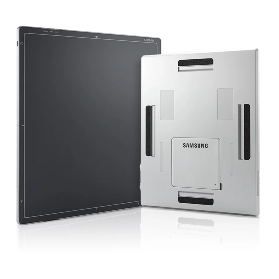
Digital Flat-Panel X-RAY Detector
Samsung Electronics Co., Ltd.
This manual is provided for the installation and operation of S4335-AW series,S4343-AW/SZ4343-W.
Please read this manual before the detector install and use.
© 2013 Samsung Electronics Co
Ltd. All rights reserved.
.,
1
Advertisement
Table of Contents

Related Manuals for Samsung S4335-AW Series


Summary of Contents for Samsung S4335-AW Series
- Page 1 (S4335-AW/AWV, S4343-AW/SZ4343-W ) Digital Flat-Panel X-RAY Detector Samsung Electronics Co., Ltd. This manual is provided for the installation and operation of S4335-AW series,S4343-AW/SZ4343-W. Please read this manual before the detector install and use. © 2013 Samsung Electronics Co Ltd. All rights reserved.
- Page 2 Revision History Version Date Page Revision Mar. 30,2018 Edition June. 26,2018 ADD WARNING ADD CAUTION(EMC) ADD Related comments on IP 54(Maintenance) ADD Version Corrected LED STATUS ADD Maintaining Water and Dust Resistance ADD IP WARNING ADD Specifications ADD APPENDICES...
-
Page 3: Table Of Contents
Maintenace, Cleaning and Disposal ........................................16 Disclaimer ..................................................18 System Overview ................................................... 19 System Overview ................................................19 S4335-AW series ..............................................19 S4343-AW/SZ4343-W ............................................. 19 System Purposes ..............................................19 Product components ............................................... 20 ... - Page 4 Battery Recharger ..............................................31 Battery ..................................................33 Operating the System Hardware ............................................... 36 Operating the System Hardware ..........................................36 Checking Connection .............................................. 36 Operation ..................................................37 Operating description ............................................. 38 Specifications ....................................................39 Appendices ....................................................40...
- Page 5 Table 5 P OWER UPPLY ESCRIPTION LED ........................................31 Table 6 B ATTERY ECHARGER NDICATE (S4335-AW series,S4343-AW/SZ4343-W) ................... 37 Table 7 CHECKING THE POWER STATUS OF COMPONENTS ............................................... 37 Table 8 P OWER TATUS ............................................38 Table 9 O PERATING TIME TABLE...
- Page 6 OWER APPLIED COMPONENTS Figure 18: X-ray exposure & image acquisition ...................................... 38 Hereby, SAMSUNG ELECTRONICS CO., LTD. declares that the radio equipment type S4335-AW series, S4343-AW/SZ4343-W are in compliance with Directive 2014/53/EU. The full text of the EU declaration of conformity is available at the following internet address: https://www.samsungmedicalsolution.com...
-
Page 7: About This Manual
About this Manual Symbols Used in This Manual The specifications and details of this manual may be changed in order to improve the product or to enhance its performance The following symbols are used throughout this manual to alert the user to the relevant safety instructions or to any useful information when using this system Symbol Name... -
Page 8: Intended For Use
Intended for use S4335-AW series,S434AW/SZ4343-W, Digital Flat Panel X-Ray Detector are indicated for digital imaging solution designed for providing general radiographic diagnosis of human anatomy targeting both adult and children. It is intended to replace film based radiographic diagnostic systems and provide more precise case diagnosis and treatment planning on a real time basis for physicians and radiologists. -
Page 9: Safety Instructions
AFETY INSTRUCTIONS Safety Instructions □In this chapter, information of safety instructions and regulations are provided. It is provided to protect users of the system from unintended safety hazard and prevent property damage, please read thoroughly and keep instructions. If additional training is required, consult your dealer or the service center of the manufacturer. -
Page 10: System Symbols
System Symbols Table 1 shows the symbols related to maintaining the safety of the patient and the user. Alternate current Direct current Protective earth (Ground) Off (power : disconnect from the main switch) On (power : connect to the main switch) Identifies terminals which, when connected together, bring various parts of a piece of equipment or of a system to the same potential. -
Page 11: Table 1 Special Symbol
Avoid contact with water No unauthorized or unlawful modification Waste electrical and electronic equipment (WEEE) Temperature limitation Marks fragile device that requires full attention when handling. Manufacturer EC Representative Table 1 S PECIAL YMBOL... -
Page 12: System Maintenance Checkpoints
System Maintenance Checkpoints To ensure the system performance and usability along with safety, regular maintenance and checking the condition are required. To secure safety of both patient and operator and to ensure the performance of the system, check the system on a regular interval. For periodic inspection of the system, consult your dealer or the manufacturer's service center. -
Page 13: Genenral Safety
Fault, damage or personal injury incurred due to use of an ancillary device which is not provided by the manufacturer. □ When Problem Occurs Should any of the following occur, immediately turn OFF the power of each instruments, unplug the power cable from the AC outlet, and contact SAMSUNG representative or distributor. WARNING ... -
Page 14: Electrical Safety
Electrical Safety □ In compliance with IEC 60601-1, this medical equipment complies with the requirements for Safety class I, type B. WARNING □ This system must be used in an environment complying with the requirements of the IEC. WARNING □... -
Page 15: Mechanical Safety
Mechanical Safety □ Never remove the cover (Detector, Power Box, Recharger, Battery Pack, and Adapter) or cables unless directed to do so by a professionally trained engineer. WARNING □ When an examination is in progress, auditory and visual communication between the patient and the system user must be possible at all times. -
Page 16: Label
The instrument must be repaired by a qualified engineer only. If it is not repaired properly, it may cause fire, electric shock, or accident. The S4335-AW series,S4343AW/SZ4343-W are rated IP54 of water-resistant and dustproof according to IEC 60529 standard. ... - Page 17 Correct Disposal of This Product (Waste Electrical & Electronic Equipment) (Applicable in countries with separate collection systems) This marking on the product, accessories or literature indicates that the product and its electronic accessories should not be disposed of with other household waste at the end of their working life. To prevent possible harm to the environment or human health from uncontrolled waste disposal, please separate these items from other types of waste and recycle them responsibly to promote the sustainable reuse of material resources.
-
Page 18: Disclaimer
Disclaimer The manufacturer assumes no liability for any failure or damage which may occur by using other company's products The manufacturer assumes no liability for any failure or damage that may occur from installing, relocating, modifying, maintaining, or repairing the equipment by any personnel other than designated personnel by the manufacturer. ... -
Page 19: System Overview
System Purposes The S4335-AW series,S4343AW/SZ4343-W are a portable digital X-ray flat panel wireless detector that can generate Images of any part of the body. This X-ray imaging system consists of an X-ray detector (an a-Si TFT sensor panel with scintillator), a power supply box, a battery recharger, battery packs and a main cable. -
Page 20: Product Components
Product components Item Part Name Product Name Description S4335-AW S4335-AWV Detector X-ray flat panel detector S4343-AW SZ4343-W DEPS9601 Source of necessary electricity Power Supply Box DEPS9601A Source of necessary electricity With DC power Input Battery Recharger MSP-90W-12VC To recharge an extra battery Battery Pack ELT-3S1PA Source for wireless connection... -
Page 21: Examination Room Components
Examination Room Components The components of The S4335-AW series,S4343AW/SZ4343-W can be divided into the examination room components and the control room Components in accordance with their installation locations. The below figure 1 shows S4335-AW series,S4343-AW/SZ4343-W Examination Components. Main cable... -
Page 22: Control Room Components
Control Room Components The control room for S4335-AW series,S4343-AW/SZ4343-W are configured as shown in Figure 2. 2. Battery Recharger IGURE Integration Information Samsung Digital X-ray systems... -
Page 23: System Components
It makes high-resolution, high-sensitive digital images. Overview The S4335-AW series,S434AW/SZ4343-W are a portable digital x-ray flat panel detector that can generate images of any part of the body. This x-ray imaging system is based on amorphous silicon sensor pixels arrayed on a flat panel for X-ray image acquisition. It makes high-resolution, high-sensitive digital images. - Page 24 Configuration of the Wireless Detector IGURE Name/Function Description This area converts the X-rays passing through the patient ① Detection Area into images. Any part of the body outside the detection area will not be captured. This cable is used for power supply and ②...
- Page 25 H/W Signal Check : The green LED Indicator Aperiodically blinks. • Wireless Mode: The green LED indicator is on. Table 4 LED S TATUS In the case of a S4335-AW series,S4343-AW/SZ4343-W detector, the LED indicator may be different depending on the particulars of the product.
- Page 26 Notes for Using the Detector Handling WARNING: Using the detector while other electronic devices are being operated nearby may affect the • performance of the detector. If you use other wireless equipment that has similar frequencies, such as smartphones, at the same time as the detector, the detector may experience wireless connection issues.
- Page 27 A sudden change in the temperature of the examination room may cause moisture to build up in the wireless detector. In the event of this happening, do not use the wireless detector until all of the moisture is removed. Using the wireless detector with moisture in it may result in unstable system operation. If air-conditioning is available, decrease the temperature gradually to reduce the temperature difference between the wireless detector and the examination room to prevent moisture build-up.
- Page 28 • To reduce the risk of infection while using the detector, the use of disposable plastic bags is recommended. Maintaining Water and Dust Resistance The S4335-AW series,S4343AW/SZ4343-W are rated IP54 water-resistant and dustproof according to IEC 60529 standard. Despite this classification, S3025-W is not impervious to water damage in any situation. It is important that all compartments are kept tightly closed.
-
Page 29: Power Supply Box
Power Supply Box IGURE OWER UPPLY Item Description ① Earth GND: Connects the power supply box to the ground. ② Inlet (100-240 Vac): Supplies power to the power supply box. Fuse: Protects the power supply box from overvoltage. ③ Switch: Turns the power supply box on and off. Power Supply Box ④... -
Page 30: Main Cable
Main Cable IGURE ABLE This cable connects the detector to the power supply box. Because the instrument’s cable is long, take care so cables do not get tangled during use. WARNING Also, be careful not to get your feet caught in the cable. Do not pull the cable by force. -
Page 31: Igure Attery Echarger
Battery Recharger The battery recharger is used for S4335-AW series, S4343-AW/SZ4343-W . You can recharge the battery and check the charge condition. IGURE ATTERY ECHARGER 1. LED: Indicates the condition of charge. This is turned off when the power is disconnected or is not recharged. -
Page 32: Igure Attery Nsert
When using the S4335-AW series,S434AW/SZ4343-W battery recharger, always use the battery (ELT-3S1PA) provided by Samsung Electronics Co. Ltd.. WARNING When using Battery recharger, Be sure to use Adapter (AD-9019A) Provided by Samsung Electronics Co. Ltd.. When moving the S4335-AW series,S434AW/SZ4343-W battery recharger, always separate the power WARNING and battery pack ... -
Page 33: Igure Attery
Battery 14 B IGURE ATTERY ① Battery terminal part When the battery use period is much shorter than the usual use time, replace the battery. • When the battery is not used for a long time, charge the battery and disconnect the power. •... -
Page 34: Igure Attery Over Nstallation
IP54 of water-resistant and dustproof according to IEC 60529 standard. The S4335-AW series,S434AW/SZ4343-W • Ensure that battery cover must be tightly closed in order to maintain water and dust resistance of IP54. Opened or loosed cover may allow water and dust to enter the device and cause damage. - Page 35 If the terminals of the battery become dirty, wipe with a dry cloth before using the battery. WARNING Be sure to use the battery in the environment designated by Samsung. Otherwise, the life of battery can be short WARNING ...
-
Page 36: Set Up
PERATING THE YSTEM ARDWARE Operating the System Hardware IP set up [My Network Places] → [Properties] → [Local Area Connection] → [Properties] → [Internet Protocol (TCP/IP)] → [Use the following IP address] IP address : 192 . 168 . 197 . 20 (Console PC) Detector IP address is 192. -
Page 37: Operation
Switching power on / off This equipment is turned on by the Power Button of each component. Table 9 lists the methods for checking the power on status of the system components. 20 P (S4335-AW series,S4343-AW/SZ4343-W) IGURE OWER APPLIED COMPONENTS Component... -
Page 38: Operating Description
Operating description Figure 21: X-ray exposure & image acquisition Item min. typ. max. unit Exposure request time (II) Before x-ray pulse start Exposure window S4335-AW Wireless S4343-AW Image transmitted SZ4343-W after exposure done S4335-AW 2.05 2.50 (IV + V + VI) Wired S4343-AW 2.35... -
Page 39: Specifications
5. S PECIFICATIONS S4335-AW S4335-AWV S4343-AW / SZ4343-W Gadolinium Cesium Iodide Cesium Iodide scintillator(CsI) Oxy-sulfide Detector Type scintillator S:Tb) (CsI) Indirect Indirect Effective Pixel Matrix 3, 040 x 2, 466 pixels 3, 040 x 3, 036 pixels Effective Pixel Area 425.6 x 345.24 mm 425.60 x 425.04 mm 140 ㎛... -
Page 40: Appendices
PPENDICES FCC Statement of Conformance Federal Communication Commission Interference Statement This equipment has been tested and found to comply with the limits for a Class A digital device, pursuant to part 15 of the FCC Rules. These limits are designed to provide reasonable protection against harmful interference when the equipment is operated in a commercial environment. - Page 41 The device could automatically discontinue transmission in case of absence of information to transmit, or operational failure. Note that this is not intended to prohibit transmission of control or signaling information or the use of repetitive codes where required by the technology.
- Page 42 Transmit Antenna Notice This radio transmitter [IC: 649E-WBW880A] has been approved by Innovation, Science and Economic Development Canada to operate with the antenna types listed below, with the maximum permissible gain indicated. Antenna types not included in this list that have a gain greater than the maximum gain indicated for any type listed are strictly prohibited for use with this device.
- Page 43 EMC Declaration 1. Compliance Statement This equipment complies with IEC 60601-1-2 EMC standards for medical devices. This equipment needs special precautions regarding EMC and needs to be installed and put into service according to the EMC information provided in the user manual. Do not use any wireless devices, including cellular phones, near the system.
- Page 44 Restriction of use of Wi-Fi using 5 GHz bands(5150 - 5350 MHz) “In the EU, the Wi-Fi function in this equipment should not be used outdoors. ≑ Wired & Wireless Interface Standard IEEE 802.3 compliant Wired Physical data rate 10/100/1000 BASE-T Standard IEEE 802.11 a/b/g/n/ac WI-FI Frequency...
- Page 45 Table1 Guidance and manufacturer’s declaration- Electromagnetic emissions This Wireless Detector is intended for use in the electromagnetic environment specified below. The user of this Wireless Detector should assure that it is used in such an environment Emission test Compliance Electromagnetic environment - guidance This Wireless Detector uses RF energy only for its internal RF emissions function.
- Page 46 Table2 Guidance and manufacturer’s declaration- Electromagnetic immunity This Wireless Detector is intended for use in the electromagnetic environment specified below. The customer or the user of this Wireless Detector should assure that it is used in such an environment. Electromagnetic IMMUNITY test IEC 60601 test level Compliance level...
- Page 47 Table3 Guidance and manufacturer’s declaration- Electromagnetic immunity This Wireless Detector is intended for use in the electromagnetic environment specified below. The customer or the user of this Wireless Detector should assure that it is used in such an environment. IEC 60601 TEST Compliance IMMUNITY test Electromagnetic environment –...
- Page 48 Table4 Recommended separation distances between portable and mobile RF communications equipment and this Wireless Detector This Wireless Detector is intended for use in an electromagnetic environment in which radiated RF disturbances are controlled. The customer or the user of this Wireless Detector can help prevent electromagnetic interference by maintaining a minimum distance between portable and mobile RF communications equipment (transmitters) and this Wireless Detector as recommended below, according to the maximum output power of the communications equipment.
- Page 49 RF exposure compliance The available scientific evidence does not show that any health problems are associated with using low power wireless devices. There is no proof, however, that these low power wireless devices are absolutely safe. Low power wireless devices emit low levels radio frequency energy (RF) in the microwave range while being used. Whereas high levels of RF can produce health effects (by heating tissue), exposure of low-level RF that does not produce heating effects causes no known adverse health effects.
Need help?
Do you have a question about the S4335-AW Series and is the answer not in the manual?
Questions and answers