
Related Manuals for Siemens Simotion TM 121C


Summary of Contents for Siemens Simotion TM 121C
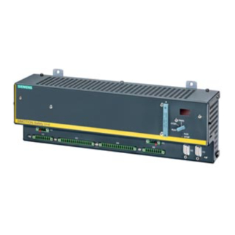
- Page 1 Application manual 06/2003 Edition simotion SIMOTION Safety Integrated Safety Unit TM 121C...
- Page 3 Preface, Table of Contents General information on SIMOTION parameterization software Safety Unit TM 121C Operating modes Safety components Application manual for presses Operating elements Procedural functions of mechanical presses Procedural functions of hydraulic presses Procedural functions of press brakes General functions Operating and fault messages Documentation 6AU1900-0DM20-0XA0...
- Page 4 Trademarks SIMATIC®, SIMOTION®, SINUMERIK® and SITOP® are registered trademarks of Siemens AG. Other designations in this document may be trademarks whose use by third parties for their own purposes may infringe on the rights of the trademark holder.
- Page 5 The contents of this Manual shall neither become a part of nor modify any prior or existing agreement, commitment or legal relationship. The sales contract contains the entire obligation entered into by Siemens. The warranty contained in the contract between the parties is the sole warranty of Siemens. Any statements contained herein do not create new warranties nor modify the existing warranty.
- Page 6 Notes © Siemens AG 2003 All Rights Reserved SIMOTION Safety Unit (AP) - Edition 06.2003...
-
Page 7: Table Of Contents
5.3 Control of press safety valves............5-43 5.4 Valve monitoring ................5-45 6 Procedural functions of hydraulic presses........6-47 6.1 Control of valves for hydraulic presses......... 6-47 6.2 Valve monitoring ................6-48 © Siemens AG 2003 All Rights Reserved SIMOTION Safety Unit (AP) - Ausgabe 06.2003... - Page 8 9 Operating and fault messages ............9-67 10 Documentation................10-71 10.1 Documentation of inputs (notes)..........10-71 10.2 Documentation of outputs (notes)..........10-72 10.3 Documentation of system data ........... 10-72 © Siemens AG 2003 All Rights Reserved viii SIMOTION Safety Unit (AP) - Ausgabe 06.2003...
-
Page 9: General Information On Parameterization Software
The entered value is saved by pressing the Accept button. A green dot appears to the left if the entry has been saved properly and completely. © Siemens AG 2003 All Rights Reserved SIMOTION Safety Unit (AP) - Edition 06.2003... - Page 10 General information on parameterization software Notes © Siemens AG 2003 All Rights Reserved 1-10 SIMOTION Safety Unit (AP) - Edition 06.2003...
-
Page 11: Operating Modes
Parameterization The assignment of the connection terminals to the operating mode is shown in Figure 2-1, left section. Figure 2-1 Operating modes © Siemens AG 2003 All Rights Reserved 2-11 SIMOTION Safety Unit (AP) - Edition 06.2003... -
Page 12: Operating Modes And Press Cycles
An operating mode type can also have several parameterizations if, for example, the number of safety devices varies. • The Setup operating mode (operating mode 1) is predefined and cannot be modified. © Siemens AG 2003 All Rights Reserved 2-12 SIMOTION Safety Unit (AP) - Edition 06.2003... -
Page 13: Setup (Operating Mode 1)
When parameterizing "Selected safety device can be disabled via terminal", other suitable safety measures must be effective for the specific machine when this parameter is activated. © Siemens AG 2003 All Rights Reserved 2-13 SIMOTION Safety Unit (AP) - Edition 06.2003... -
Page 14: Single Stroke (Operating Mode 2)
The same applies if the "Transfer through input terminal" parameter is selected for the "Transfer of START command". Parameterization Figure 2-4 Enabling of operating mode 2 © Siemens AG 2003 All Rights Reserved 2-14 SIMOTION Safety Unit (AP) - Edition 06.2003... -
Page 15: Continuous Stroke (Operating Mode 3)
Depending on the selections made in the enable mask, the press either stops in the TDC or comes to an immediate standstill. Parameterization Figure 2-5 Enabling of operating mode 3 © Siemens AG 2003 All Rights Reserved 2-15 SIMOTION Safety Unit (AP) - Edition 06.2003... -
Page 16: Changeover (Operating Mode 4)
Safety measures may have to implemented to safeguard the machine. Parameterization Figure 2-6 Enabling of operating mode 4 © Siemens AG 2003 All Rights Reserved 2-16 SIMOTION Safety Unit (AP) - Edition 06.2003... -
Page 17: Automatic Continuous Stroke (Operating Mode 5)
In this mode, the two-hand control acts as a command device only (not a safety device). The operator must be protected by additional safety equipment, e.g. ESPE! © Siemens AG 2003 All Rights Reserved 2-17 SIMOTION Safety Unit (AP) - Edition 06.2003... - Page 18 30 s or when a safety device or a continuous stroke stop (BDC or immediate stop) was activated. Parameterization Figure 2-9 Enabling of operating mode 5 © Siemens AG 2003 All Rights Reserved 2-18 SIMOTION Safety Unit (AP) - Edition 06.2003...
-
Page 19: Single-Stroke Espe (Operating Mode 6)
Single-stroke ESPE (operating mode 6) Using a light curtain to control the press is described in the Control Elements chapter. Parameterization Figure 2-10 Enabling of operating mode 6 © Siemens AG 2003 All Rights Reserved 2-19 SIMOTION Safety Unit (AP) - Edition 06.2003... - Page 20 Operating modes Notes © Siemens AG 2003 All Rights Reserved 2-20 SIMOTION Safety Unit (AP) - Edition 06.2003...
-
Page 21: Safety Components
Without the implementation of additional safety measures, safety gates and safety guards without a restart inhibit are not suitable for hazardous areas that can be walked through. © Siemens AG 2003 All Rights Reserved 3-21 SIMOTION Safety Unit (AP) - Edition 06.2003... -
Page 22: Parameterization Of Safety Components
Safety components 3.1 Parameterization of safety components Figure 3-1 EMERGENCY OFF safety functions Figure 3-2 Safety guard safety functions © Siemens AG 2003 All Rights Reserved 3-22 SIMOTION Safety Unit (AP) - Edition 06.2003... - Page 23 The problem is eliminated by completely opening and reclosing the gate. Figure 3-4 Engaging lock safety functions © Siemens AG 2003 All Rights Reserved 3-23 SIMOTION Safety Unit (AP) - Edition 06.2003...
-
Page 24: Example Of Safety Component Wiring
Safety components 3.2 Example of safety component wiring Clock voltage X2.5 X2.1 X3.5 X4.5 Figure 3-5 Example of EMERGENCY OFF wiring © Siemens AG 2003 All Rights Reserved 3-24 SIMOTION Safety Unit (AP) - Edition 06.2003... - Page 25 Safety components Clock voltage X2.6 X2.2 X3.6 X4.6 Figure 3-6 Example of safety guard wiring © Siemens AG 2003 All Rights Reserved 3-25 SIMOTION Safety Unit (AP) - Edition 06.2003...
- Page 26 Safety components Notes © Siemens AG 2003 All Rights Reserved 3-26 SIMOTION Safety Unit (AP) - Edition 06.2003...
-
Page 27: Control Elements
(fail safe). • The operating modes in which the two-hand buttons are to be disabled are selected on the right side of the parameterization mask. © Siemens AG 2003 All Rights Reserved 4-27 SIMOTION Safety Unit (AP) - Edition 06.2003... - Page 28 Control elements Parameterization Figure 4-1 Two-hand control Example of wiring Clock voltage X2.5 X2.6 X2.1 X2.2 X3.1 X3.2 X4.1 X4.2 Figure 4-2 Two-hand control © Siemens AG 2003 All Rights Reserved 4-28 SIMOTION Safety Unit (AP) - Edition 06.2003...
-
Page 29: Determining The Safety Distance
Safety Unit data sheet connection of the lag meter for determining the reaction time of the machine (empirical Machine measurement) use the poorest of 10 measurement values! © Siemens AG 2003 All Rights Reserved 4-29 SIMOTION Safety Unit (AP) - Edition 06.2003... -
Page 30: Foot Switch
This has the same function as the two-hand control with the exception that it has only one NC and one NO contact. A maximum of 3 foot switches can be connected. Parameterization Figure 4-3 Operation of the foot switch © Siemens AG 2003 All Rights Reserved 4-30 SIMOTION Safety Unit (AP) - Edition 06.2003... -
Page 31: Acknowledge Button For Group Acknowledgement
This button is used to reset signals requiring acknowledgement, such as error messages and safety guard acknowledgement messages. Parameterization Figure 4-5 Operation of the acknowledge button © Siemens AG 2003 All Rights Reserved 4-31 SIMOTION Safety Unit (AP) - Edition 06.2003... -
Page 32: Electro-Sensitive Protective Equipment (Espe)
The following light curtains have been tested with the control unit: - Type 3RG78..., by Siemens in safety or clock mode (clock mode as of July 03) - TypeC4000 advanced, by Sick in safety or clock mode Others upon request ©... -
Page 33: Determining The Safety Distance With Espe
Safety Unit data sheet connection of lag meter for determining the reaction time of the machine (empirical Machine measurement) use the poorest of 10 measurement values! © Siemens AG 2003 All Rights Reserved 4-33 SIMOTION Safety Unit (AP) - Edition 06.2003... -
Page 34: Control Function With Light Curtain
The interruption must last longer than 100 ms. • The interruption must take place at the top dead center. • The previous interruption may not lie farther back than 30 s. © Siemens AG 2003 All Rights Reserved 4-34 SIMOTION Safety Unit (AP) - Edition 06.2003... -
Page 35: Restart Inhibit Of Light Curtain In Clock Mode
The restart inhibit is acknowledged by the command device. Either a separate button or a two-hand control can be used as a command device. Parameterization Figure 4-6 Operating the light curtain © Siemens AG 2003 All Rights Reserved 4-35 SIMOTION Safety Unit (AP) - Edition 06.2003... -
Page 36: Restart Inhibit Of Light Curtain In Safety Mode
The restart inhibit is activated in the event of an intervention during a hazardous movement. This is indicated by the flashing of the fault lamp. It is reset by means of the acknowledge button for group acknowledgement. © Siemens AG 2003 All Rights Reserved 4-36 SIMOTION Safety Unit (AP) - Edition 06.2003... -
Page 37: Emergency Off Output Signal
If the output signal is activated using a mode selector, it is not activated until after acknowledgement. • The acknowledgement request is output via the corresponding message. © Siemens AG 2003 All Rights Reserved 4-37 SIMOTION Safety Unit (AP) - Edition 06.2003... - Page 38 Control elements Example of wiring Figure 4-9 EMERGENCY OFF output signal © Siemens AG 2003 All Rights Reserved 4-38 SIMOTION Safety Unit (AP) - Edition 06.2003...
-
Page 39: Procedural Functions Of Mechanical Presses
170° to 180° up to 340° Run-up cam (mechanical) Dynamic cam (electronic) 10° up to 320° Overtravel cam (mechanic) Figure 5-1 Example of a cam setting © Siemens AG 2003 All Rights Reserved 5-39 SIMOTION Safety Unit (AP) - Edition 06.2003... - Page 40 320° to 340°, for example, and takes over the TDC switch-off on a falling edge. Parameterization Figure 5-2 Mechanical operation – Cam monitoring system © Siemens AG 2003 All Rights Reserved 5-40 SIMOTION Safety Unit (AP) - Edition 06.2003...
- Page 41 Procedural functions of mechanical presses Example of wiring Clock voltage Electronic cam switchgear, PLC or initiator X3.9 X3.10 Run-up cam Overtravel cam Dynamic TDC switch-off Figure 5-3 Cam evaluation © Siemens AG 2003 All Rights Reserved 5-41 SIMOTION Safety Unit (AP) - Edition 06.2003...
-
Page 42: Speed Monitor
The overtravel angle may not exceed 90°. Parameterization Figure 5-4 Mechanical operation – Speed monitor © Siemens AG 2003 All Rights Reserved 5-42 SIMOTION Safety Unit (AP) - Edition 06.2003... -
Page 43: Control Of Press Safety Valves
This function is used to control two press safety valves (clutch and brake). Both valves are controlled simultaneously, each via two channels (P/M-switching) with 24 V/2 A. Figure 5-6 Extras - Output pin assignment (mech.) © Siemens AG 2003 All Rights Reserved 5-43 SIMOTION Safety Unit (AP) - Edition 06.2003... - Page 44 Procedural functions of mechanical presses Example of wiring Figure 5-7 Press safety valves © Siemens AG 2003 All Rights Reserved 5-44 SIMOTION Safety Unit (AP) - Edition 06.2003...
-
Page 45: Valve Monitoring
If an electrical valve monitor is not in use, monitoring must be accomplished by means of other measures with a comparable degree of safety (hydraulic or electric). Parameterization Figure 5-8 Mechanical operation – Watchdog timer © Siemens AG 2003 All Rights Reserved 5-45 SIMOTION Safety Unit (AP) - Edition 06.2003... - Page 46 Procedural functions of mechanical presses Notes © Siemens AG 2003 All Rights Reserved 5-46 SIMOTION Safety Unit (AP) - Edition 06.2003...
-
Page 47: Procedural Functions Of Hydraulic Presses
To detect a short circuit between these two signals, one of them must be supplied via the encoder clock (e. g. by using a mechanical switch). Parameterization Figure 6-1 Extras - Output pin assignment (hydr.) © Siemens AG 2003 All Rights Reserved 6-47 SIMOTION Safety Unit (AP) - Edition 06.2003... -
Page 48: Valve Monitoring
If an electrical valve monitor is not in use, monitoring must be accomplished by means of other measures with a comparable degree of safety (hydraulic or electric). © Siemens AG 2003 All Rights Reserved 6-48 SIMOTION Safety Unit (AP) - Edition 06.2003... - Page 49 Procedural functions of hydraulic presses Example of wiring Figure 6-4 Valve monitoring © Siemens AG 2003 All Rights Reserved 6-49 SIMOTION Safety Unit (AP) - Edition 06.2003...
- Page 50 Procedural functions of hydraulic presses Notes © Siemens AG 2003 All Rights Reserved 6-50 SIMOTION Safety Unit (AP) - Edition 06.2003...
-
Page 51: Procedural Functions Of Press Brakes
7.3 Control elements The control elements (two-hand control, foot switch, acknowledge button for group acknowledgement) do not require special handling for the folding functionality. © Siemens AG 2003 All Rights Reserved 7-51 SIMOTION Safety Unit (AP) - Edition 06.2003... -
Page 52: Generating Enables
(HIGH level), but can change its state during the movement. This function can be disabled when no additional start condition is required (default). © Siemens AG 2003 All Rights Reserved 7-52 SIMOTION Safety Unit (AP) - Edition 06.2003... - Page 53 A jog function can be implemented with the second control element. This function is primarily used during press motion. If the job mode is activated during the fast downward movement, the system automatically © Siemens AG 2003 All Rights Reserved 7-53 SIMOTION Safety Unit (AP) - Edition 06.2003...
-
Page 54: Folding Function
ANDed. A falling edge on an active access protection de-energizes the valves. The access protection is not evaluated beyond the mute point (function required for light curtain). © Siemens AG 2003 All Rights Reserved 7-54 SIMOTION Safety Unit (AP) - Edition 06.2003... -
Page 55: Watchdog Timer
The valve run time can be variably parameterized from 20 to 2000 ms. The feedback input can be defined as an NO or NC contact. © Siemens AG 2003 All Rights Reserved 7-55 SIMOTION Safety Unit (AP) - Edition 06.2003... -
Page 56: Dynamic Valve Monitoring
For this reason, a response delay can be parameterized for the valve. The response delay for the valve monitor can be variably set to between 20 and 2000 ms. © Siemens AG 2003 All Rights Reserved 7-56 SIMOTION Safety Unit (AP) - Edition 06.2003... -
Page 57: Valve Control
The control is reset as soon as a safety device "responds", the "fast" request is set, the upward movement is initiated or the operating mode is changed. © Siemens AG 2003 All Rights Reserved 7-57 SIMOTION Safety Unit (AP) - Edition 06.2003... - Page 58 Valve 1 (valve pair 1) is de-energized immediately. • Switching the "fast downwards speed" request signal level from "1" to "0" Valve 2 (valve pair 2) is de-energized immediately. © Siemens AG 2003 All Rights Reserved 7-58 SIMOTION Safety Unit (AP) - Edition 06.2003...
-
Page 59: Information On Functionality
This function is fail-safe (HIGH level for enable). The proximity switches must be installed on the machine according to the desired maximum tilt. © Siemens AG 2003 All Rights Reserved 7-59 SIMOTION Safety Unit (AP) - Edition 06.2003... -
Page 60: Moving" And "Distance" Access Protection
3. Access protection 2 is now active. In this case, a MUTE point cannot be parameterized in operating mode 3 since access protection would otherwise be deactivated beginning with the MUTE point. © Siemens AG 2003 All Rights Reserved 7-60 SIMOTION Safety Unit (AP) - Edition 06.2003... -
Page 61: Application Examples And Procedural Functions
For this example, it is assumed that a foot switch and an access protection (dual- channel E1/E2) have been parameterized for mode 2. The valves are controlled via variant 2. © Siemens AG 2003 All Rights Reserved 7-61 SIMOTION Safety Unit (AP) - Edition 06.2003... -
Page 62: Multiple Operator Control With Foot Switch
For this example, it is assumed that two foot switches and an access protection (dual-channel E1/E2) have been parameterized for mode 4. The valves are controlled via variant 2. © Siemens AG 2003 All Rights Reserved 7-62 SIMOTION Safety Unit (AP) - Edition 06.2003... -
Page 63: General Functions
Foot switch 2 can be selected using an NO contact (it can be deactivated). The deactivation input should be switched by the selector switch for single operator/multi-operator control. © Siemens AG 2003 All Rights Reserved 8-63 SIMOTION Safety Unit (AP) - Edition 06.2003... -
Page 64: Single Operator Control Via 2 Foot Switches And Operating Error Monitor
2 was activated, a suitable message is output and the machine is prevented from starting. The system stops if a control element that was not selected is activated during a press movement. © Siemens AG 2003 All Rights Reserved 8-64 SIMOTION Safety Unit (AP) - Edition 06.2003... -
Page 65: Output Assignment (0.5 A)
Safety devices closed (+acknowledge) This function signalizes that all safety devices that are active in the respective operating mode are closed, or are closed and acknowledged. © Siemens AG 2003 All Rights Reserved 8-65 SIMOTION Safety Unit (AP) - Edition 06.2003... - Page 66 This function signalizes that the upward movement of the hydraulic press is being performed. This means that the press safety valves and the valves for the upward movement are being controlled. © Siemens AG 2003 All Rights Reserved 8-66 SIMOTION Safety Unit (AP) - Edition 06.2003...
-
Page 67: Operating And Fault Messages
See 2) F035 Error, input X4.16 See 2) F036 – F039 Not assigned F040 Error, input X3.1 See 2) F041 Error, input X3.2 See 2) © Siemens AG 2003 All Rights Reserved 9-67 SIMOTION Safety Unit (AP) - Edition 06.2003... - Page 68 3) Check the wiring and correct if necessary. A more precise statement on the source of the error can only be made after evaluation of the error entries in the diagnosis buffer. © Siemens AG 2003 All Rights Reserved 9-68 SIMOTION Safety Unit (AP) - Edition 06.2003...
- Page 69 Safety gate closed – ready for acknowledge This error can only be acknowledged in the Setup operating mode If the safety gate display is parameterized for the fault lamp. © Siemens AG 2003 All Rights Reserved 9-69 SIMOTION Safety Unit (AP) - Edition 06.2003...
- Page 70 Operating error (foot switch 1 was actuated but is not active) F241 Operating error (foot switch 2 was actuated but is not active) F242 Operating error (foot switch 3 was actuated but is not active) © Siemens AG 2003 All Rights Reserved 9-70 SIMOTION Safety Unit (AP) - Edition 06.2003...
-
Page 71: Documentation
10 Documentation 10.1 Documentation of inputs (notes) Pin Description Cable Notes © Siemens AG 2003 All Rights Reserved 10-71 SIMOTION Safety Unit (AP) - Edition 06.2003... -
Page 72: Documentation Of Outputs (Notes)
A complete function text must be performed after changes are made to the parameterization, whether after the equipment is exchanged or after the memory card is replaced (see Chapter 2.2 Device manual). © Siemens AG 2003 All Rights Reserved 10-72 SIMOTION Safety Unit (AP) - Edition 06.2003... - Page 73 Paper industry Food industry Textile industry Control technology Transportation Mechanical engineering Other _ _ _ _ _ _ _ _ _ _ _ _ _ Petrochemical industry © Siemens AG 2003 All Rights Reserved SIMOTION Safety Unit (AP) - Edtion 06.2003...
- Page 74 Comments/suggestions Your comments and suggestions assist us in improving the quality and usability of our documentation. Please fill in this questionnaire at the next opportunity and send it back to Siemens. Title of manual: Safety Unit TM 121C Application manual for presses Order no.
- Page 76 Siemens AG Automation and Drives Motion Control Systems © Siemens AG 2003 P.O. Box 3180, D – 91050 Erlangen Subject to change without prior notice. Federal Republic of Germany Order no.: 6AU1900-0DM20-0XA0 www.ad.siemens.de Printed in the Federal Republic of Germany...
Need help?
Do you have a question about the Simotion TM 121C and is the answer not in the manual?
Questions and answers