Siemens FDO421 - Photoelectric Detector Installation Manual
- Installation instructions (2 pages) ,
- Installation instructions (4 pages)
Advertisement
INSTALLATION INSTRUCTIONS
These instructions are written in accordance with the installation guidelines of NFPA 72, National Fire Alarm Code, The Installation of Fire Alarm Systems.

Detection Device Storage
DO NOT install this detection device until all construction is completed.
DO NOT store this detection device where it can be contaminated by dirt, dust, or humidity.
DETECTOR PLACEMENT
Although no specific spacings are set for the detectors used for a clean air application, use 30 foot center spacing (900 sq ft) from NFPA Standard 72 initiating devices chapter, if practical, as a guide or starting point for a detector installation layout. This spacing, however, is based on ideal conditions–smooth ceiling, no air movement, and no physical obstructions. In some applications, therefore, considerably less area is protected adequately by each smoke detector. This is why it is mandatory to closely follow the installation drawings. In all installations place the detector on the ceiling, a minimum of 6 inches from a side wall, or on a wall, 6 inches from the ceiling.
If you have any questions regarding detector placement, follow the drawings provided or approved by Siemens Industry, Inc., or by its authorized distributors. This is extremely important! The detector placements shown on these drawings were chosen after a careful evaluation of the area that is protected. Such factors as air currents, temperature, humidity, pressure, and the nature of the fire load were carefully considered. Especially noted were the room or area configuration and the type of ceiling (sloped or flat, smooth or beamed). Siemens Industry, Inc.'s extensive experience in the design of the system assures the best detector placement by following these drawings.
TO AVOID NUISANCE ALARMS
Do not locate the detectors where excessive smoke concentrations exist under normal conditions, or in areas of prolonged high relative humidity where condensation occurs.
Do not locate the detectors next to an oil burner, kitchen, or garage where exhaust fumes can trigger an alarm. Other causes of false alarms are dust accumulation, heavy concentrations of steam, heavy pipe or cigar smoke, and certain aerosol sprays.
AIR CURRENTS
Before a detector can sense a fire, the products of combustion or smoke must travel from the fire to the detector. This travel is especially influenced by air currents; therefore, consider air movement when designing the system. While combustion products tend to rise, drafts from hallways, air diffusers, fans, etc., may help or hinder the travel of combustion products to the detector. When positioning a detector at a particular location, give consideration to windows and doors, both open and closed, to ventilating systems, both in and out of operation, and to other factors influencing air movement. Do not install a detector in the air stream of a room air supply diffuser. It is better to position a detector closer to an air return.

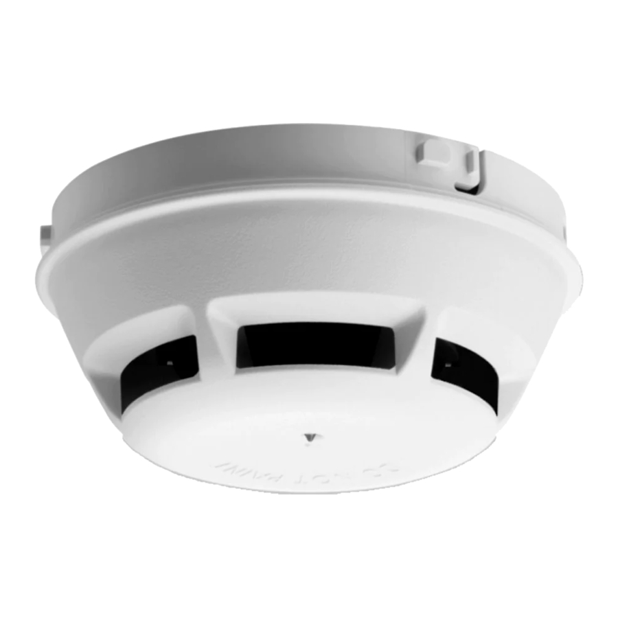
Figure 1 FDO421
The distance that products of combustion or smoke travel from a fire to the detector is not usually the shortest linear route. Combustion products or smoke usually rise to the ceiling, then spread out. Average ceiling heights of 8 to 10 feet do not abnormally affect detector response. High ceilings, located in churches, warehouses, auditoriums, etc., do affect detector response and should be considered.
SPECIAL CEILING CONSTRUCTION FACTORS
Ceiling obstructions change the natural movement of air and combustion products. Depending on the direction of smoke travel, joists and beams can slow the movement of heated air and smoke, while pockets between them can contain a reduced level of smoke. Take obstructions created by girders, joists, beams, air conditioning ducts, or architectural design into consideration when determining area protection. Refer to the Initiating Devices chapter of NFPA Standard 72 for Location and Spacing requirements for specific types of construction; e.g. beam, suspended, level, sloped and peaked ceilings. The detector is also compatible with the following mechanical protection guard model: STI-9604 (see www.STI-USA.com for details).
TEMPERATURE – HUMIDITY – PRESSURE – AIR VELOCITY
The temperature range for the FDO421 detector is 32°F (0°C) to 120°F (49°C). Use the detector in environments where the humidity does not exceed 95% (non-condensing). Normal changes of atmospheric pressure do not affect detector sensitivity. The air velocity range is 0-4000 ft/min for open areas applications and direct in air duct applications. Follow detector spacing and location requirements in NFPA 72 Chapter for High Air Movement Areas and Control of Smoke Spread.
LED INDICATOR OPERATION
The Model FDO421 contains an LED indicator capable of flashing either one of three distinct colors: green, yellow, or red. During each flash interval, the microprocessor-based detector monitors the following:
- Smoke in its sensing chamber
- Smoke sensitivity is within the range indicated on the nameplate label
- Internal sensors and electronics
Based on the results of the monitoring, the LED indicator flashes the following:
| Flash Color | Condition | Flash Interval (Seconds) |
| Green* | Normal supervisory operation. Smoke sensitivity is within rated limits. | 10 |
| Yellow | Detector is in trouble and needs replacement. | 4 |
| Red | Alarm | 1 |
| No Flashes | Detector is not powered, or replacement is needed. | - |
| *LED can be turned off. Please follow the corresponding description of the Panel used. | ||
DETECTOR PROGRAMMING
Each detector must be programmed to respond to a unique system address between 001 - 252.
- To program the detector address, use the Model DPUDevice Programming Unit. Refer to the DPU Manual, P/N 315-033260.
- Record the loop and device number (system address) forthe detector on the detector label and on the base to prevent installing the detector in the wrong base. The optional DPU label printer can be used for this purpose.
Each detector provides pre-programmed parameter sets which can be selected by the panel. Please follow the corresponding descriptions of the panel used.
- Sensitive
- Standard
- Robust
- Air Duct
 NOTE: When using this detector direct in air duct applications, be sure the detector is set to the parameter "Air Duct."
WIRING
Detector bases for Model FDO421 should be connected as shown in Figure 2.

Figure 2 Installation and Wiring Diagram
*The relay contacts are shown after System reset, which represents the non-alarm condition.
**FDO421 is a polarity insensitive detector. Line 1 and Line 2 can be either line of the loop.
DETECTOR MOUNTING
To ensure proper installation of the detector head into the base, be sure the wires are properly dressed at installation:
- Position all wires flat against the base.
- Take up all slack in the outlet box
- Route wires away from connector terminals.
TO INSTALL DETECTOR HEAD:
- Rotate detector counterclockwise while gently pressing on it until the detector seats fully into base.
- Then rotate the detector clockwise until it stops and locks inplace. Insert optional locking screw (Order Model LK-11).
TO REMOVE DETECTOR HEAD:
- Loosen locking screw, if installed. Then rotate the detectorcounterclockwise until stop is reached.
- Pull detector out of base.
DETECTOR TESTING
Only qualified service personnel should test. To assure proper operation of the detector, both the Sensitivity and Functional Test should be conducted. The minimum test schedule may be found in the current edition of NFPA 72.
SENSITIVITY MEASUREMENT
The sensitivity of FDO421 detectors can be tested individually using the DPU. Refer to the DPU Manual, P/N 315-033260. The sensitivity can also be measured by the panel. Follow the instructions of the panel used.
FUNCTIONAL TEST
Perform a functional (Go, No-Go) test by activating the detector using Test Gas, P/N 500-649750, following the instruction on the gas canister label. This test is simply used to ensure that smoke can enter the sensing chamber and alarm the control panel when the detector reaches the programmed obscuration (concentration) level.
The FDO421 detectors can also be tested individually using the DPU. Refer to the DPU Manual, P/N 315-033260.
DETECTOR MAINTENANCE
The control unit automatically indicates the trouble message for the FDO421 detector whose smoke chamber changes to the level where the set sensitivity cannot be maintained. In such circumstances, the detector may require replacement.
UNDER NO CIRCUMSTANCES IS THE DETECTOR HEAD TO BE DISASSEMBLED. NO REPAIRS SHOULD BE ATTEMPTED.
DO NOT PAINT
The detector/base plastic is marked DO NOT PAINT. This is intended to prohibit painting during routine maintenance of the occupancy which can affect proper operation of the detector.

Documents / Resources
References
Download manual
Here you can download full pdf version of manual, it may contain additional safety instructions, warranty information, FCC rules, etc.
Download Siemens FDO421 - Photoelectric Detector Installation Manual
Advertisement


Need help?
Do you have a question about the FDO421 and is the answer not in the manual?
Questions and answers