Table of Contents
Advertisement
Quick Links
Download this manual
See also:
User Manual
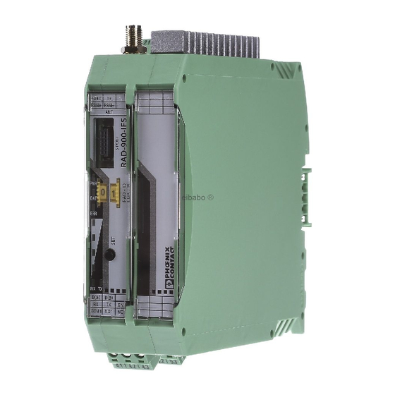
RAD-900-IFS
900 MHz wireless transceiver (transmitter and re-
ceiver) with RS-232 and RS-485 interface, can be ex-
tended with I/O extension modules
INTERFACE
Data sheet
3225_en_A
1
Description
Wireless communication is based on Trusted Wireless 2.0
technology. The high demand for a interference-free data
transmission using the license-free 900 MHz band, in partic-
ular via the use of the FHSS method (FHSS) and 128-bit
data encryption (AES), is fulfilled.
In addition to an RS-232 and RS-485 2-wire interface, the
RAD-900-IFS wireless module supports the option of di-
rectly connecting up to 32 I/O extension modules in the sta-
tion structure via the TBUS DIN rail connector.
Addressing of the wireless module and I/O mapping of the I/
O extension modules is carried out quickly and easily by
means of the thumbwheel on the front. Programming knowl-
edge is not required.
The PSI-CONF configuration and diagnostics software for
special functionality and diagnostic options in the wireless
module is available free of charge.
This product is only for export outside of the European Economic area.
Make sure you always use the latest documentation.
It can be downloaded from the product at phoenixcontact.net/products.
This data sheet is valid for all products listed on the following page:
© PHOENIX CONTACT
2013-03-25
Features
–
Flexible network applications: I/O data, serial data,
PLC/Modbus RTU mode
–
Adjustable data rates for the wireless interface
–
Easy point-to-point or network structures (star, repeat-
er)
–
Quick and easy startup thanks to simple wireless mod-
ule addressing using the thumbwheel on the front
–
Integrated RS-232 and RS-485 interface
–
Can be extended with up to 32 I/O modules per station
via T-BUS (hot-swappable)
–
128-bit data encryption (AES)
–
Unique network addressing via plug-in configuration
memory (RAD-CONF) for secure, parallel operation of
multiple networks (different RF bands)
–
Data rates and ranges can be adjusted
Advertisement
Table of Contents

Related Manuals for Phoenix Contact RAD-900-IFS


Summary of Contents for Phoenix Contact RAD-900-IFS
-
Page 1: Description
– Easy point-to-point or network structures (star, repeat- In addition to an RS-232 and RS-485 2-wire interface, the RAD-900-IFS wireless module supports the option of di- – Quick and easy startup thanks to simple wireless mod- rectly connecting up to 32 I/O extension modules in the sta- ule addressing using the thumbwheel on the front tion structure via the TBUS DIN rail connector. -
Page 2: Table Of Contents
RAD-900-IFS Table of contents Description ..........................1 Table of contents ........................2 Ordering data .......................... 3 Technical data ......................... 4 Safety regulations and installation notes.................. 7 ......................... 7 Installation notes ....................... 7 Installation and operation ............7 Safety regulations for installation in potentially explosive areas ........................ -
Page 3: Ordering Data
USB data cable (USB-A on IFS plug) for communicating between PCs and RAD-CABLE-USB 2903447 PHOENIX CONTACT devices with an IFS data port, e.g., RAD-2400-IFS. Power supply for diagnostics and configuration via the USB port of the PC. Cable length: 2 m. -
Page 4: Technical Data
RAD-900-IFS Accessories Type Order No. Pcs. / Pkt. Antenna extension cable, length: 80 ft RAD-CAB-LMR400-80 2867393 Antenna extension cable, length: 100 ft RAD-CAB-LMR400-100 2867238 Antenna extension cable, length: 150 ft RAD-CAB-LMR600-150 2885184 Antenna extension cable, length: 200 ft RAD-CAB-LMR900-200 2885197... - Page 5 RAD-900-IFS Wireless interface Data transmission rate ( adjustable ) 16 kbps 125 kbps 250 kbps 500 kbps Receiver sensitivity -112.00 dBm (16 kbps) -105.00 dBm (125 kbps) -102.00 dBm (250 kbps) -95.00 dBm (500 kbps) Transmission power max. 1 W (adjustable)
- Page 6 RAD-900-IFS Ambient conditions Ambient temperature (operation) -40 °C ... 70 °C -40 °F ... 158 °F Ambient temperature (storage/transport) -40 °C ... 85 °C -40 °F ... 185 °F Permissible humidity (operation) 20 % ... 85 % Permissible humidity (storage/transport) 20 % ...
-
Page 7: Safety Regulations And Installation Notes
RAD-900-IFS Safety regulations and installation WARNING: Risk of electric shock notes During operation, certain parts of this device may carry hazardous voltages. Disregarding Installation notes this warning may result in damage to equip- ment and/or serious personal injury. Please note that, in combination with anten-... -
Page 8: Conformance
RAD-900-IFS Conformance NOTE: This equipment has been tested and found to comply with the limits for a Class A digital de- vice, pursuant to part 15 of the FCC rules. These limits are designed to provide reason- able protection against harmful interference when the equipment is operated in a commer- cial environment. -
Page 9: Installation
RAD-900-IFS Installation Pos. Designation RSMA antenna connection (socket) NOTE: electrostatic discharge! Test output RSSI (0...3 V DC) for evaluation of the The device contains components that can be wireless signal strength damaged or destroyed by electrostatic dis- Device supply (+24 V DC, GND) charge. -
Page 10: Display And Diagnostic Elements
RAD-900-IFS Display and diagnostic elements ERR LED Nine LEDs on the RAD-900-IFS indicate the operating sta- The red ERR LED indicates the error status, e.g., no corre- tus. sponding output module found (e.g., incorrect address- ing). Off: No error Flashing:... - Page 11 RAD-900-IFS LED bar graph As the full transmission power and the reception amplifier are activated by default, signals may be superimposed. The LED bar graph indicates the receive signal strength. Increase the distance between devices. LEDs Receive signal RSSI (in...
-
Page 12: Assembly/Removal
Connection station with I/O extension modules Up to 32 different I/O extension modules can be connected to each RAD-900-IFS wireless module via the TBUS DIN rail connector (see accessories). Data is transmitted and power is supplied to the I/O extension modules via the bus foot. -
Page 13: Connecting The Cables
Connecting the cables Activating/deactivating the termination network • Crimp ferrules to the wires. The RAD-900-IFS wireless module is operated on a 2-wire Permissible cable cross section: 0.2...2.5 mm². bus cable. For correct operation of the bus system, termina- • Insert the wire with ferrule into the corresponding con- tion networks are required for the RS-485 bus connection. - Page 14 9-pos. DSUB pin assignment In RS-485 mode, an RS-485 network with several I/O de- The RAD-900-IFS provides a D-SUB 9-pos. female connec- vices can be created. Use a twisted pair bus cable to con- tor for attaching RS-232 serial devices.
-
Page 15: Startup And Configuration
RAD-900-IFS Startup and configuration All RAD-900-IFS wireless modules have the same default configuration. Default settings Operating mode: I/O data mode (wire in/wire out) Data communication is only possible using I/O extension modules. Wireless interface Net ID: RF band: Encryption: Network structure:... -
Page 16: Setting The Station Address (Rad-Id)
The devices in a wireless network are addressed using the station (I/O mapping). thumbwheel on the front of the RAD-900-IFS wireless mod- The I/O MAP address may only appear once in the network. ule. -
Page 17: Plc/Modbus Rtu Mode
For configuration, you need the RAD-CABLE-USB cable The CONFSTICK is inserted in the S-PORT (item 4 in Figure (Order No. 2903447). 1) of the RAD-900-IFS wireless module. Once applied, the information is loaded in an internal memory. PLC/Modbus RTU mode... -
Page 18: Copying Device Settings To New Network Devices
– Operating mode The copying of the parameters starts automatically. – Network ID Press and hold the "SET" button on the RAD-900-IFS – RF band for at least six seconds. The DAT LED flashes to indi- – Data rate of the wireless interface cate the transfer is started.
Need help?
Do you have a question about the RAD-900-IFS and is the answer not in the manual?
Questions and answers