
Subscribe to Our Youtube Channel
Related Manuals for Phoenix Contact RAD-900-DAIO6


Summary of Contents for Phoenix Contact RAD-900-DAIO6
- Page 1 Radioline - 900 MHz wireless transmission system for serial interfaces and I/O signals User manual UM EN RAD-900-IFS(DAIO6)
-
Page 2: I/O Extension Modules
Order No. RAD-900-IFS 2901540 RAD-900-DAIO6 2702877 I/O extension modules: RAD-AI4-IFS 2901537 RAD-PT100-4-IFS 2904035 RAD-AO4-IFS 2901538 RAD-DI4-IFS 2901535 RAD-DI8-IFS 2901539 RAD-DOR4-IFS 2901536 RAD-DO8-IFS 2902811 RAD-DAIO6-IFS 2901533 PHOENIX CONTACT GmbH & Co. KG • Flachsmarktstraße 8 • 32825 Blomberg • Germany phoenixcontact.com... -
Page 3: Table Of Contents
Safety regulations for installation in potentially explosive areas......7 Conformance......................8 Short description.........................9 RAD-900-IFS wireless module ................9 2.1.1 Structure .....................10 RAD-900-DAIO6....................11 2.2.1 Structure .....................12 Description of I/O extension modules ..................15 RAD-AI4-IFS - analog extension module with four inputs ........16 3.1.1 Structure ....................16 3.1.2... - Page 4 Process data in PLC/Modbus RTU mode ..........55 RAD-RS485-IFS modules..................55 Installation..........................57 DIN rail-mounted devices (RAD-900-IFS)............57 4.1.1 Mounting/removal ................57 4.1.2 Connecting wires ................59 4.1.3 Connecting the power supply ...............59 4.1.4 Serial interfaces ...................60 4.1.5 Connecting the antenna ...............62 2/138 PHOENIX CONTACT 3827_en_B...
- Page 5 5.7.3 Wireless module in PLC/Modbus RTU dual mode .......81 Starting up the RAD-900-DAIO6................82 5.8.1 Setting the address of the RAD-900-DAIO6 via the thumbwheel ..82 5.8.2 RAD-900-DAIO6 in PLC/Modbus RTU dual mode .......83 Startup time of the wireless station ..............84 Serial data mode (RAD-900-IFS only)..................85 Frame-based data transmission ................87...
- Page 6 PLC/Modbus RTU dual mode ....................93 Configuration via PSI-CONF software ..............94 Addressing I/O extension modules ..............95 Watchdog ......................95 Addressing I/O extension modules and RAD-900-DAIO6 with Modbus RTU ......97 Modbus function codes ..................97 Modbus protocol....................97 Addressing registers....................98 Module type and error code register ..............99 9.4.1...
-
Page 7: For Your Safety
– Qualified application programmers and software engineers. The users must be familiar with the relevant safety concepts of automation technology as well as applicable standards and other regulations. 5/138 3827_en_B PHOENIX CONTACT... -
Page 8: Safety Notes
The PSI-CONF configuration and diagnostic software can be used to configure the transmit power. Operation of the wireless system is only permitted if accessories available from Phoenix Contact are used. The use of other accessory components may invalidate the device approval status Installation and operation Follow the installation instructions. -
Page 9: Safety Regulations For Installation In Potentially Explosive Areas
Install the RAD-900-IFS into a housing (control or distributor box) with at least IP54 protection (EN 60529) and is certified for use in Class I, Div. 2 or Zone 2. The RAD-900-DAIO6 meets the IP65 degree of protection does not require an additional housing. -
Page 10: Conformance
Canada. To reduce potential radio interference to other users, the antenna type and its gain should be so chosen that the equivalent isotropically radiated power (EIRP) is not more than that necessary for successful communication. – IC certificate: IC4720C-SHR900 8/138 PHOENIX CONTACT 3827_en_B... -
Page 11: Short Description
Unique network addressing via plug-in configuration memory (RAD-CONF) for secure, parallel operation of multiple networks with different RF bands – Data rates and ranges can be configured using the PSI-CONF software – UL/cUL listed for installation in Class I, Div. 2/Zone 2 environments 9/138 3827_en_B PHOENIX CONTACT... -
Page 12: Structure
D-SUB 9 connector (RS-232 interface) RS-232/485 serial interface status LED (RX/TX) LED bar graph for displaying the wireless signal strength ERR status LED, red (communication error) DAT status LED, green (BUS communication) PWR status LED, green (supply voltage) 10/138 PHOENIX CONTACT 3827_en_B... -
Page 13: Rad-900-Daio6
Figure 2-2 RAD-900-IFS circuit diagram RAD-900-DAIO6 The RAD-900-DAIO6 is a NEMA 4X-rated wireless device with one analog input, one analog output, two digital inputs, and two digital outputs directly integrated. It does not have a serial interface. The RAD-900-DAIO6 may be AC- or DC-powered, and addressing of the wireless module and I/O mapping of the extension modules is carried out quickly and easily by means of the thumbwheel on the front. -
Page 14: Structure
COM NO NC ON-OFF FUSE COM NO NC I COM PWR +I -I 230V LINK Figure 2-3 RAD-900-DAIO6 structure Table 2-2 RAD-900-DAIO6 structure Item Designation N-type antenna 12-pos. programming interface (S-PORT) DIP switches for configuring I/O RAD ID address setting via thumbwheel... -
Page 15: Dip Switches Of The Rad-Daio6-Ifs
Analog OUT RESET Analog OUT HOLD Digital OUT1 RESET Digital OUT1 HOLD Digital OUT2 RESET Digital OUT2 HOLD Circuit diagram RF LINK RAD-ID RSSI + RSSI - µC +24VDC/120VAC 0V/N LOOP Figure 2-4 RAD-900-DAIO6 circuit diagram 13/138 3827_en_B PHOENIX CONTACT... - Page 16 RAD-900-... 14/138 PHOENIX CONTACT 3827_en_B...
-
Page 17: Description Of I/O Extension Modules
Four digital inputs RAD-DI4-IFS 2901535 Eight digital inputs or RAD-DI8-IFS 2901539 two pulse inputs Four digital relay RAD-DOR4-IFS 2901536 outputs Eight digital transistor - RAD-DO8-IFS 2902811 outputs Analog/digital One analog RAD-DAIO6-IFS 2901533 input/output, two digital wide-range - inputs/outputs 15/138 3827_en_B PHOENIX CONTACT... -
Page 18: Rad-Ai4-Ifs - Analog Extension Module With Four Inputs
Analog input 3 for 2-, 3-, 4-wire measuring transducers Analog input 4 for 2-, 3-, 4-wire measuring transducers ERR status LED, red (communication error) DAT status LED, green (bus communication) PWR status LED, green (supply voltage) 16/138 PHOENIX CONTACT 3827_en_B... -
Page 19: Basic Circuit Diagram
In PLC/Modbus RTU mode, the setting of the input signals is evaluated for error diagnostics. With the setting 4 mA ... 20 mA, it is, for example, possible to detect an open circuit. OFF ON DIP-1 Figure 3-3 DIP switches of the RAD-AI4-IFS 17/138 3827_en_B PHOENIX CONTACT... -
Page 20: Diagnostic Leds
The green PWR LED indicates the supply voltage status. No supply voltage Supply voltage OK DAT LED The green DAT LED indicates the bus communication status. No communication Flashing Configuration and addressing mode Cyclic data communication 18/138 PHOENIX CONTACT 3827_en_B... -
Page 21: Setting The I/O-Map Address
The process image of the I/O extension module consists of six data words. For additional information, please refer to Section 3.1, “RAD-AI4-IFS - analog extension module with four inputs”. I/O module Module type Number of Address area Function code registers RAD-AI4-IFS 30xx0 ... 30xx5 fc 04 19/138 3827_en_B PHOENIX CONTACT... -
Page 22: Rad-Pt100-4-Ifs - Extension Module With Four Temperature Inputs
. The measuring errors that occur may lead to the entire measurement to become useless. Please observe the diagrams in Section “Measuring errors using 2-wire connection technology” on page 22. With 2-wire technology, you need an insertion bridge between terminals x.2 and x.3. 20/138 PHOENIX CONTACT 3827_en_B... - Page 23 +I and -I must have the same value. This allows you to subtract the established cable resistance from the measurement result and to get the Pt 100 platinum resistance value. IO-MAP ϑ U– I– µC Figure 3-6 3-wire connection technology 21/138 3827_en_B PHOENIX CONTACT...
-
Page 24: Measuring Errors Using 2-Wire Connection Technology
Temperature measuring error for A = 0.5 mm Temperature measuring error for A = 1.0 mm Temperature measuring error for A = 1.5 mm (Measuring error valid for: copper cable χ = 57 m/Ωmm = 25°C and Pt 100 sensor) 22/138 PHOENIX CONTACT 3827_en_B... -
Page 25: Systematic Temperature Measuring Error Δt Depending On The Cable Cross Section A
Due to there being two cable resistances in the measuring system, the value must be doubled. Using the average temperature coefficient α = 0.385 Ω/K for Pt 100, the absolute measuring error in Kelvin can be determined for platinum sensors according to DIN standards. 23/138 3827_en_B PHOENIX CONTACT... -
Page 26: Shielding Of The Sensor Cables
ϑ U– U– I– I– Figure 3-11 Shielding with 3-wire connection technology 2-wire connection technology with twisted pair cables and shielding IO-MAP ϑ I– µC Figure 3-12 2-wire connection technology with twisted pair cables and shielding 24/138 PHOENIX CONTACT 3827_en_B... -
Page 27: Structure
Pt 100 input 3 for 2- and 3-wire sensors Pt 100 input 4 for 2- and 3-wire sensors ERR status LED, red (communication error) DAT status LED, green (bus communication) PWR status LED, green (supply voltage) 25/138 3827_en_B PHOENIX CONTACT... -
Page 28: Basic Circuit Diagram
The RAD-PT100-4-IFS I/O extension module uses a total of three LEDs to indicate the operating states. Figure 3-16 Diagnostic LEDs of the RAD-PT100-4-IFS PWR LED The green PWR LED indicates the supply voltage status. No supply voltage Supply voltage OK 26/138 PHOENIX CONTACT 3827_en_B... -
Page 29: Setting The I/O-Map Address
The process image of the I/O extension module consists of six data words. For additional information, please refer to Section 3.2, “RAD-PT100-4-IFS - extension module with four temperature inputs”. I/O module Module type Number of Address area Function registers code RAD-PT100-4-IFS 30xx0 ... 30xx5 fc 04 27/138 3827_en_B PHOENIX CONTACT... -
Page 30: Rad-Ao4-Ifs - Analog Extension Module With Four Outputs
Metal foot catch for DIN rail fixing Analog output 3 (alternatively current or voltage) Analog output 4 (alternatively current or voltage) ERR status LED, red (communication error) DAT status LED, green (bus communication) PWR status LED, green (supply voltage) 28/138 PHOENIX CONTACT 3827_en_B... -
Page 31: Basic Circuit Diagram
(e.g., interruption of the wireless connection). Any changes in the setting of the DIP switches will be directly applied. – RESET = Output value is set to 0 – HOLD = Hold last valid output value OFF ON DIP-1 Figure 3-19 DIP switches of the RAD-AO4-IFS 29/138 3827_en_B PHOENIX CONTACT... -
Page 32: Diagnostic Leds
The green PWR LED indicates the supply voltage status. No supply voltage Supply voltage OK DAT LED The green DAT LED indicates the bus communication status. No communication Flashing Configuration and addressing mode Cyclic data communication 30/138 PHOENIX CONTACT 3827_en_B... -
Page 33: Setting The I/O-Map Address
The process image of the I/O extension module consists of six data words. For additional information, please refer to Section 3.3, “RAD-AO4-IFS - analog extension module with four outputs”. I/O module Module type Number of Address area Function code registers RAD-AO4-IFS 40xx0 ... 40xx5 fc 03, 16 31/138 3827_en_B PHOENIX CONTACT... -
Page 34: Rad-Di4-Ifs - Digital Extension Module With Four Inputs
Digital input as wide-range input Digital input as wide-range input Status LEDs for digital inputs DI1 ... DI4 ERR status LED, red (communication error) DAT status LED, green (bus communication) PWR status LED, green (supply voltage) 32/138 PHOENIX CONTACT 3827_en_B... -
Page 35: Basic Circuit Diagram
The green PWR LED indicates the supply voltage status. No supply voltage Supply voltage OK DAT LED The green DAT LED indicates the bus communication status. No communication Flashing Configuration and addressing mode Cyclic data communication 33/138 3827_en_B PHOENIX CONTACT... -
Page 36: Setting The I/O-Map Address
The process image of the I/O extension module consists of two data words. For additional information, please refer to Section 3.4, “RAD-DI4-IFS - digital extension module with four inputs”. I/O module Module type Number of Address area Function code registers RAD-DI4-IFS 30xx0 ... 30xx1 fc 04 34/138 PHOENIX CONTACT 3827_en_B... -
Page 37: Rad-Di8-Ifs - Digital Extension Module With Eight Inputs
Connection option for DIN rail connector DIN rail Metal foot catch for DIN rail fixing Digital inputs 5 + 6 Digital inputs 7 + 8, DI7: pulse input 2 Status LEDs for digital inputs DI1 ... DI8 35/138 3827_en_B PHOENIX CONTACT... -
Page 38: Basic Circuit Diagram
In pulse counter mode, the DI1 and DI7 pulse inputs are activated, 0 Hz ... 100 Hz pulses. The pulse counter function is only available in PLC/Modbus RTU mode. Set the operating mode using the PSI-CONF software (from Section 5.6, “Configuration via PSI-CONF software” onwards). 36/138 PHOENIX CONTACT 3827_en_B... -
Page 39: Functions In Pulse Counter Mode
Disconnect the device power supply and then reconnect the voltage. Reset counter state via the Modbus RTU register • Reset the counter states via Modbus RTU as follows: – DI1: bit 0 = 1 (register 40xx1) – DI7: bit 1 = 1 (register 40xx1) 37/138 3827_en_B PHOENIX CONTACT... -
Page 40: Diagnostic Leds
The red ERR LED indicates the error status. No error Flashing Slow (1.4 Hz) I/O-MAP address changed or mode switched using DIP switch 1, but not yet applied Fast (2.8 Hz) No bus communication Critical internal error 38/138 PHOENIX CONTACT 3827_en_B... -
Page 41: Setting The I/O-Map Address
Setting the I/O-MAP address for the RAD-DI8-IFS Thumbwheel Description setting 01 ... 99 I/O-MAP address Delivery state **, 1* ... 9* Setting not permitted *1 ... *9 Interface System slave address, for use with other Interface System (IFS) master devices 39/138 3827_en_B PHOENIX CONTACT... -
Page 42: Process Data In Plc/Modbus Rtu Mode
Address area Function code registers 30xx0 ... 30xx1 fc 04 Static mode Static inputs 30xx0 ... 30xx5 fc 04 Pulse counter Pulse inputs RAD-DI8-IFS mode 40xx0 ... 40xx1 fc 03, 16 Pulse counter Reset counter mode states 40/138 PHOENIX CONTACT 3827_en_B... -
Page 43: Rad-Dor4-Ifs - Digital Extension Module With Four Outputs
Relay output 3 with floating PDT contact Relay output 4 with floating PDT contact Status LEDs for the relay outputs DO1 ... DO4 ERR status LED, red (communication error) DAT status LED, green (bus communication) PWR status LED, green (supply voltage) 41/138 3827_en_B PHOENIX CONTACT... -
Page 44: Basic Circuit Diagram
HOLD = Hold last output value OFF ON DIP-1 Figure 3-30 DIP switches of the RAD-DOR4-IFS Table 3-10 DIP switches of the RAD-DOR4-IFS DIP switch Setting Output signal Digital OUT1 RESET Digital OUT1 HOLD Digital OUT2 RESET 42/138 PHOENIX CONTACT 3827_en_B... -
Page 45: Diagnostic Leds
The green PWR LED indicates the supply voltage status. No supply voltage Supply voltage OK DAT LED The green DAT LED indicates the bus communication status. No communication Flashing Configuration and addressing mode Cyclic data communication 43/138 3827_en_B PHOENIX CONTACT... -
Page 46: Setting The I/O-Map Address
Section 3.6, “RAD-DOR4-IFS - digital extension module with four outputs”. I/O module Module type Number of Address area Function code registers RAD-DOR4-IFS 10 40xx0 ... 40xx1 fc 03, 16 44/138 PHOENIX CONTACT 3827_en_B... -
Page 47: Rad-Do8-Ifs - Digital Extension Module With Eight Outputs
Transistor outputs 1 + 2 Supply voltage for outputs 1 ... 4 DIP switches for setting the output behavior of the transistor outputs (hold/reset) White thumbwheel for setting the I/O-MAP address Connection option for DIN rail connector 45/138 3827_en_B PHOENIX CONTACT... -
Page 48: Basic Circuit Diagram
(e.g., interruption of the wireless connection). Any changes in the setting of the DIP switches will be directly applied. – RESET = Output value is set to 0 – HOLD = Hold last output value 46/138 PHOENIX CONTACT 3827_en_B... -
Page 49: Diagnostic Leds
= not connected, DIP switches 3 and 4 have no function 3.7.4 Diagnostic LEDs The RAD-DO8-IFS I/O extension module uses a total of eleven LEDs to indicate the operating states. Figure 3-35 Diagnostic LEDs of the RAD-DO8-IFS 47/138 3827_en_B PHOENIX CONTACT... - Page 50 The yellow DO1 ... DO8 LEDs indicate the status of the digital outputs. DO1 ... DO4 Flashing Short circuit at one output or several outputs 1 ... 4 DO5 ... DO8 Flashing Short circuit at one output or several outputs 5 ... 8 48/138 PHOENIX CONTACT 3827_en_B...
-
Page 51: Setting The I/O-Map Address
Section 3.7, “RAD-DO8-IFS - digital extension module with eight outputs”. I/O module Module type Number of Address area Function code registers 40xx0 ... 40xx1 fc 03.16 Outputs RAD-DO8-IFS 30xx0 ... 30xx1 fc 04 Short-circuit detection 49/138 3827_en_B PHOENIX CONTACT... -
Page 52: Rad-Daio6-Ifs - Analog/Digital Extension Module With Six Channels
The analog output is designed as active output. You can either select a current signal 0/4 mA ... 20 mA or a voltage signal 0 V ... 10 V. Use either a current or voltage output at the analog output. 50/138 PHOENIX CONTACT 3827_en_B... -
Page 53: Structure
Relay output with floating PDT contact Status LEDs of the digital DO1 ... DO2 Status LEDs of the digital DI1 ... DI2 inputs ERR status LED, red (communication error) DAT status LED, green (bus communication) PWR status LED, green (supply voltage) 51/138 3827_en_B PHOENIX CONTACT... -
Page 54: Basic Circuit Diagram
RESET = Output value is set to 0 – HOLD = Hold last output value Digital outputs – RESET = Relay drops out – HOLD = Hold last valid state Figure 3-38 DIP switches of the RAD-DAIO6-IFS 52/138 PHOENIX CONTACT 3827_en_B... -
Page 55: Diagnostic Leds
The green PWR LED indicates the supply voltage status. No supply voltage Supply voltage OK DAT LED The green DAT LED indicates the bus communication status. No communication Flashing Configuration and addressing mode Cyclic data communication 53/138 3827_en_B PHOENIX CONTACT... -
Page 56: Setting The I/O-Map Address
Setting the I/O-MAP address for the RAD-DAIO6-IFS Thumbwheel Description setting 01 ... 99 I/O-MAP address Delivery state **, 1* ... 9* Setting not permitted *1 ... *9 Interface System slave address, for use with other Interface System (IFS) master devices 54/138 PHOENIX CONTACT 3827_en_B... -
Page 57: Process Data In Plc/Modbus Rtu Mode
OFF ON OFF ON OFF ON OFF ON DIP-1 DIP-1 DIP-1 DIP-1 DIP-1 DIP-1 LINK LINK LINK RX TX RX TX RX TX D(A) D(B) D(A) D(B) D(A) D(B) RS-485 RS-485 RS-485 Figure 3-40 Typical RAD-RS485-IFS installation 55/138 3827_en_B PHOENIX CONTACT... - Page 58 RAD-900-... 56/138 PHOENIX CONTACT 3827_en_B...
-
Page 59: Installation
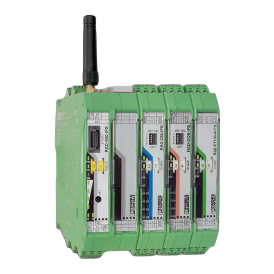
Mount the wireless module to the left and the I/O extension modules exclusively to the right of the wireless module. The individual extension modules can be arranged in any order. Figure 4-1 Radioline connection station with up to 32 I/O extension modules 57/138 3827_en_B PHOENIX CONTACT... -
Page 60: Figure 4-2 Mounting And Removal
Use a suitable screwdriver to release the locking mechanism on the snap-on foot of the device (see Figure 4-2, E). Hold onto the device by the housing cover and carefully tilt it upwards. Carefully lift the device off the DIN rail connector and the DIN rail. 58/138 PHOENIX CONTACT 3827_en_B... -
Page 61: Connecting Wires
In the case of a connection station, it is sufficient to supply the first device in the group. NOTE: The power supply must be connected to terminals 1.1 and 1.2. Power supply via the DIN rail connector (TBUS) is not permitted. 59/138 3827_en_B PHOENIX CONTACT... -
Page 62: Serial Interfaces
I/O devices. Install this bus cable with a termination network at the two furthest points. • Connect the single wires of the data cable to the COMBICON plug-in screw terminal block (Figure 2-1, item 10). • Make sure the signal assignment is correct. 60/138 PHOENIX CONTACT 3827_en_B... -
Page 63: Figure 4-5: Rs-485 Interface Pin Assignment
If you are not sure whether the device to be connected is of DTE or DCE type, measure the voltage between TX and GND in the idle state. – If the voltage measures approximately -5 V, it is a DTE device. – If the voltage measures approximately 0 V, it is a DCE device. 61/138 3827_en_B PHOENIX CONTACT... -
Page 64: Connecting The Antenna
Observe the installation instructions of the antenna and the “Installation and operation” on page 6. Observe the maximum permissible emitted transmission power of 36 dBm. The transmission power can be calculated as: device transmission power + antenna gain - cable attenuation Reduce the device transmission power, if necessary. 62/138 PHOENIX CONTACT 3827_en_B... -
Page 65: Wall-Mounted Devices (Rad-900-Daio6)
Wall-mounted devices (RAD-900-DAIO6) 4.2.1 Mounting The RAD-900-DAIO6 includes mounting feet for installing the device on a vertical surface. Loosen the four screws securing the cover and remove the cover. Attach the mounting feet to the RAD-900-DAIO6 in the desired orientation using the included screws, flat washers and lockwashers. -
Page 66: Wire Entry
– Avoid mounting in direct sunlight to minimize the effects of solar loading (heating). – Installation of a sun shield is recommended over the RAD-900-DAIO6 when it is mounted in direct sunlight and the ambient temperature can exceed 45°C. 4.2.2 Wire entry The RAD-900-DAIO6 is supplied with two 1/2-in. -
Page 67: Connecting Power
When powered by an AC voltage source, the maximum temperature is 65°C. WARNING: The fuse protects the RAD-900-DAIO6 in case of an overcurrent event or if the selector switch is in the wrong position. In order to prevent damage to the wireless module, Phoenix Contact recommends the installation of a surge arrester. -
Page 68: Connecting The Antenna
+ antenna gain - cable attenuation Reduce the device transmission power, if necessary. If the antenna is removed and re-installed or a cable is attached for a remote antenna, torque the antenna or cable connector between 0.7 and 1.1 Nm. 66/138 PHOENIX CONTACT 3827_en_B... -
Page 69: Configuration And Startup
Hold down the SET button located on the front of the device and switch the supply voltage on. Press and hold the SET button until the DAT LED flashes. Resetting via PSI-CONF software Select “Wireless, RAD-900-IFS” on the “Device Selection” page. Select “Local Device”. Select “Set device to factory default configuration”. 67/138 3827_en_B PHOENIX CONTACT... -
Page 70: Firmware Update
(e.g., additional Radioline networks in the 900 MHz band), then a configuration memory can be used (see “Configuration via CONFSTICK” on page 71). For configuring extended settings of the wireless modules, it is also possible to use the PSI-CONF software (from page 74 onwards). 68/138 PHOENIX CONTACT 3827_en_B... - Page 71 In serial data mode, multiple controllers or serial I/O devices are networked easily and quickly using wireless technology. In this way, serial RS-232 or RS-485 cables can be replaced. Each wireless module must be configured using the PSI-CONF software (from page 74 onwards). 69/138 3827_en_B PHOENIX CONTACT...
- Page 72 Dual mode combines the PLC/Modbus RTU mode and the serial data mode. Serial Modbus devices can be connected to the RS-232 or RS-485 ports, and connect I/O extension modules to each wireless module in the network. 70/138 PHOENIX CONTACT 3827_en_B...
-
Page 73: Setting The Address Of The Wireless Module Via The Thumbwheel
ID are allowed to connect with each other. Each individual network device must be configured. Only one CONFSTICK is needed for all wireless modules in the network. After configuration, remove the CONFSTICK from the wireless module. 71/138 3827_en_B PHOENIX CONTACT... - Page 74 Read in has been completed when the DAT LED lights up once. The new parameters are activated. Remove the CONFSTICK from the wireless module. Repeat this process for each individual wireless module in the network. 72/138 PHOENIX CONTACT 3827_en_B...
-
Page 75: Copying Device Settings Via Memory Stick
Insert the memory stick in the S port of the wireless module. The copying of parameters is started automatically. Wait until the light sequence stops. The write process has been completed. Remove the memory stick from the wireless module. 73/138 3827_en_B PHOENIX CONTACT... -
Page 76: Reading The Memory Stick
For additional information on the USB cable, please refer to the RAD-CABLE-USB package slip. The latest documentation can be downloaded at phoenixcontact.net/products. Install the software and the USB driver for the RAD-CABLE-USB cable. Follow the software wizard. 74/138 PHOENIX CONTACT 3827_en_B... -
Page 77: Extended Configuration, Individual Settings
The lower the data transmission speed of the wireless interface, the higher the receiver sensitivity and thereby the range. Adjust the data transmission speed of the wireless interface to the respective application using the PSI-CONF software (default setting = 125 kbps). 75/138 3827_en_B PHOENIX CONTACT... - Page 78 25 km 125 kbps -105 dBm -135 dBm 35 km (default setting) 16 kbps -112 dBm -142 dBm 80 km Figure 5-7 PSI-CONF software: Wizard, Step 3 Figure 5-8 PSI-CONF software: Setting the data transmission speed 76/138 PHOENIX CONTACT 3827_en_B...
-
Page 79: Device Settings
In I/O data mode (default upon delivery), both interfaces are deactivated. To activate the serial interface, select the “Serial data,” “PLC/Modbus RTU mode,” or “PLC/Modbus RTU dual mode” network application under “Network Settings”. Only use one interface per wireless module. Parallel operation of both interfaces is not possible. 77/138 3827_en_B PHOENIX CONTACT... - Page 80 Repeater chains are used to circumvent obstacles or to set up redundant wireless paths by means of several repeaters. The “Allowed Parents” tab is only available if the “Line/Mesh” network type has been selected. Figure 5-11 PSI-CONF software: Individual Settings, Allowed Parents 78/138 PHOENIX CONTACT 3827_en_B...
-
Page 81: Starting Up I/O Extension Modules
I/O MAP address. +24 V RSSI RSSI OFF ON DIP-1 RX TX D(A) D(B) +24 V RSSI RSSI OFF ON DIP-1 RX TX D(A) D(B) Figure 5-13 RAD-DAIO6-IFS assignment: analog/digital inputs and outputs 79/138 3827_en_B PHOENIX CONTACT... -
Page 82: Setting The Address Of The Extension Modules Via The Thumbwheel
Interface System slave address, for use with other Interface System (IFS) master devices The following conditions must be met: – Assign a maximum of 1 ... 99 addresses to the extension modules in the entire wireless network. 80/138 PHOENIX CONTACT 3827_en_B... -
Page 83: Wireless Module In Plc/Modbus Rtu Dual Mode
– Output modules may not have the same I/O-MAP address as input modules on a single wireless device (station). Exception: Output modules with the same I/O-MAP address may appear several times at the same station. 81/138 3827_en_B PHOENIX CONTACT... -
Page 84: Starting Up The Rad-900-Daio6
– Assign a maximum of 1 ... 99 addresses to the RAD-900-DAIO6 in the entire wireless network. If the address is set to 01, the RAD-900-DAIO6 may only be used in point-to- point mode with another RAD-900-DAIO6. Wireless module in I/O data mode The RAD-900-DAIO6 may be used to create a point-to-point or point-to-multipoint connection with RAD-900-IFS devices. -
Page 85: Rad-900-Daio6 In Plc/Modbus Rtu Dual Mode
Configuration and startup – The RAD-900-DAIO6 may be used to create a point-to-point connection with another RAD-900-DAIO6. In this case, one RAD-900-DAIO6 must have its address set to 01 and the other must be set to 02. Figure 5-15 Thumbwheel addressing of the RAD-900-DAIO6 in point-to-point mode Wireless module in PLC/Modbus RTU mode –... -
Page 86: Startup Time Of The Wireless Station
Startup time of a wireless station = 15 seconds + (number of I/O modules x 3 seconds) Accordingly, a complete wireless station with 32 I/O extension modules requires a startup time of 111 seconds. Only after this period of time has elapsed is the wireless station ready for operation. 84/138 PHOENIX CONTACT 3827_en_B... -
Page 87: Serial Data Mode (Rad-900-Ifs Only)
When operating the network in serial data mode, it may not be possible to diagnose all devices. In this case, stop the serial application in order to allow for complete diagnostics. Use PSI-CONF software to assign different serial settings to the devices under “Individual Settings”. 85/138 3827_en_B PHOENIX CONTACT... - Page 88 Follow the software wizard. • Once you have run through all steps of the wizard, save the project and transmit it to the wireless modules. Figure 6-2 PSI-CONF software: Wizard, Step 3 Figure 6-3 PSI-CONF software: Wizard, Step 4 86/138 PHOENIX CONTACT 3827_en_B...
-
Page 89: Frame-Based Data Transmission
IdleMin FrameEnd that is permitted between two characters in a frame. Otherwise the frame might be fragmented. Frame 1 Frame 2 NOT OK Idle Idle Idle FrameEnd FrameEnd Figure 6-5 Frame-based data transmission: T parameter FrameEnd 87/138 3827_en_B PHOENIX CONTACT... - Page 90 Radioline wireless system. • In order to adapt data transmission to other protocols, it is possible to adapt the and T parameters. Set the interface parameters under “Individual FrameEnd IdleMin Settings”. Figure 6-6 PSI-CONF software: Individual Settings 88/138 PHOENIX CONTACT 3827_en_B...
-
Page 91: Plc/Modbus Rtu Mode
You can connect I/O extension modules to each wireless device in the network. A wireless network can have a maximum of 99 extension modules. Use the white thumbwheel to set the I/O-MAP addresses. Figure 7-1 PLC/Modbus RTU mode 89/138 3827_en_B PHOENIX CONTACT... -
Page 92: Configuration Via Psi-Conf Software
1; 2 Number of data bits Modbus address 1 ... 247 The Modbus connection between the controller and the wireless module can be monitored via a watchdog. For additional information on the watchdog, refer to page 91. 90/138 PHOENIX CONTACT 3827_en_B... -
Page 93: Addressing I/O Extension Modules
If the watchdog is activated and Modbus communication interrupted, the red ERR LED will flash on all wireless modules in the network. Depending on the DIP switch settings, the out- put modules issue the corresponding hold or reset value. 91/138 3827_en_B PHOENIX CONTACT... -
Page 94: 2/138 Phoenix Contact 3827_En_B
RAD-900-... 92/138 PHOENIX CONTACT 3827_en_B... -
Page 95: Plc/Modbus Rtu Dual Mode
You can connect I/O extension modules to each wireless device in the network. A wireless station can have a maximum of 32 extension modules. Use the white thumbwheel to set the I/O-MAP addresses. Figure 8-1 PLC/Modbus RTU dual mode 93/138 3827_en_B PHOENIX CONTACT... -
Page 96: Configuration Via Psi-Conf Software
1; 2 Number of data bits Modbus address 1 ... 247 The Modbus connection between the controller and the wireless module can be monitored via a watchdog. For additional information on the watchdog, refer to page 95. 94/138 PHOENIX CONTACT 3827_en_B... -
Page 97: Addressing I/O Extension Modules
If the watchdog is activated and Modbus communication interrupted, the red ERR LED will flash on all wireless modules in the network. Depending on the DIP switch settings, the output modules issue the corresponding hold or reset value. 95/138 3827_en_B PHOENIX CONTACT... - Page 98 RAD-900-... 96/138 PHOENIX CONTACT 3827_en_B...
-
Page 99: Addressing I/O Extension Modules And Rad-900-Daio6 With Modbus Rtu
Addressing I/O extension modules and RAD-900-DAIO6 with Modbus RTU Addressing I/O extension modules and RAD-900-DAIO6 with Modbus RTU Modbus function codes In the Modbus protocol, the function codes define which data is to be read or written. With a single request, the registers 1 ... 123 can be read or written. -
Page 100: Addressing Registers
3xxxx is already defined by the function code field. Function codes 03 and 16 In order to read/write registers 40032 ... 40039, you must enter 0031 (hex001F) as the start address. The address area 4xxxx is already defined by the function code field. 98/138 PHOENIX CONTACT 3827_en_B... -
Page 101: Module Type And Error Code Register
Addressing I/O extension modules and RAD-900-DAIO6 with Modbus RTU Module type and error code register You can read the module type and data currentness of the I/O extension modules from the registers 30xx0 and 40xx0. Table 9-3 Module type and currentness of data... -
Page 102: Assigning I/O Extension Modules To The Register
I/O data is stored in the Modbus memory map. You can find a complete overview of the Modbus memory map from page 109 onwards. The RSSI signal register can be found starting on page 113. 100/138 PHOENIX CONTACT 3827_en_B... -
Page 103: Rad-Ai4-Ifs Process Data
Addressing I/O extension modules and RAD-900-DAIO6 with Modbus RTU 9.5.1 RAD-AI4-IFS process data I/O module Module type Number of Address area Function registers code RAD-AI4-IFS 30xx0 ... 30xx5 fc 04 xx = I/O-MAP address set using the thumbwheel 30xx1 Reserved 30xx2 Analog input 1 (terminal point 2.x) -
Page 104: Rad-Pt100-4-Ifs Process Data
30xx2 Pt 100 input 1 (terminal point 2.x) 30xx3 Pt 100 input 2 (terminal point 3.x) 30xx4 Pt 100 input 3 (terminal point 4.x) 30xx5 Pt 100 input 4 (terminal point 5.x) 30xx6 ... 30xx9 Reserved 102/138 PHOENIX CONTACT 3827_en_B... -
Page 105: Rad-Ao4-Ifs Process Data
Addressing I/O extension modules and RAD-900-DAIO6 with Modbus RTU 9.5.3 RAD-AO4-IFS process data I/O module Module type Number of Address area Function registers code RAD-AO4-IFS 40xx0 ... 40xx5 fc 03, 16 xx = I/O-MAP address set using the thumbwheel 40xx1... -
Page 106: Rad-Di4-Ifs Process Data
04 Static mode Static inputs 30xx0 ... 30xx5 fc 04 Pulse counter Pulse inputs RAD-DI8-IFS mode 40xx0 ... 40xx1 fc 03, 16 Pulse counter Reset counter mode states xx = I/O-MAP address set using the thumbwheel 104/138 PHOENIX CONTACT 3827_en_B... - Page 107 Addressing I/O extension modules and RAD-900-DAIO6 with Modbus RTU 30xx1 Digital inputs DI1 ... DI8 (static mode) DI8 DI7 DI6 DI5 DI4 DI3 DI2 DI1 Terminal point 30xx2 DI1: 32-bit pulse input, pulse counter mode (terminal point 2.x) Counter state DI1, low word...
-
Page 108: Rad-Dor4-Ifs Process Data
I/O module Module type Number of Address area Function registers code RAD-DOR4-IFS 10 40xx0 ... 40xx1 fc 03, 16 xx = I/O-MAP address set using the thumbwheel 40xx1 Digital outputs Terminal point 40xx2 ... 40xx9 Reserved 106/138 PHOENIX CONTACT 3827_en_B... -
Page 109: Rad-Do8-Ifs Process Data
Addressing I/O extension modules and RAD-900-DAIO6 with Modbus RTU 9.5.7 RAD-DO8-IFS process data I/O module Module type Number of Address area Function registers code 40xx0 ... 40xx1 fc 03.16 Outputs RAD-DO8-IFS 30xx0 ... 30xx1 fc 04 Short-circuit detection xx = I/O-MAP address set using the thumbwheel... -
Page 110: Rad-Daio6-Ifs And Rad-900-Daio6 Process Data
RAD-900-... 9.5.8 RAD-DAIO6-IFS and RAD-900-DAIO6 process data I/O module Module Number of Address area Function type ID registers code (inputs) 30xx0 ... 30xx2 fc 04 RAD-DAIO6-IFS (outputs) 40xx0 ... 40xx2 fc 03, 16 xx = I/O-MAP address set using the thumbwheel... -
Page 111: Complete Overview Of The Modbus Memory Map
Addressing I/O extension modules and RAD-900-DAIO6 with Modbus RTU 9.5.9 Complete overview of the Modbus memory map I/O input data, address area 30010 ... 30999, I/O output data, address area 40010 ... 40999 Modbus function code 04 Modbus function code 03, 16... - Page 112 X X X X X X X X X X X X X X X X X X X X X X X X X X X X X X X X 30xx6 ... 30xx9 reserved 40xx6 ... 40xx9 reserved 110/138 PHOENIX CONTACT 3827_en_B...
- Page 113 Addressing I/O extension modules and RAD-900-DAIO6 with Modbus RTU I/O input data, address area 30010 ... 30999 I/O output data, address area 40010 ... 40999 Modbus function code 04 Modbus function code 03, 16 RAD-PT100-4-IFS I/O- High byte 15 ... 8 Low byte 7 ...
-
Page 114: Error Codes And Formats For Analog Input And Output Values
30000 20 mA 10 V 7F00 32512 21.67 mA 10.84 V Analog RAD-DAIO6-IFS and RAD-900-DAIO6 inputs and outputs Table 9-8 Representation of analog RAD-DAIO6-IFS values Data word dec/error code 0 ... 20 mA 4 ... 20 mA 0 V ... 10 V... -
Page 115: Rssi Signal Register
Addressing I/O extension modules and RAD-900-DAIO6 with Modbus RTU Error codes and formats for Pt 100 values Table 9-9 Representation of the RAD-PT100-4-IFS Pt 100 values Data word RAD-PT100-4-IFS RAD-AO4-IFS Pt 100 input analog output dec / error code -50°C ... +250°C 0 mA ... - Page 116 RAD-900-... 114/138 PHOENIX CONTACT 3827_en_B...
-
Page 117: 10 Detecting And Removing Errors
-60 dBm 2.5 V LED 2 -85 dBm -80 dBm -75 dBm -70 dBm 2.0 V LED 1 -95 dBm -90 dBm -85 dBm -80 dBm 1.5 V LINK LED LINK LINK LINK LINK ~1.0 V 115/138 3827_en_B PHOENIX CONTACT... -
Page 118: Detecting And Removing Errors: Wireless Module
• Switch the mains on, restore the power supply. probably switched off. • Ensure the power select switch is in the correct position for the type of power (RAD-900-DAIO6 only) • Check the fuse (RAD-900-DAIO6) DAT off No communication between •... - Page 119 (at least 1 m in the horizontal direction or 0.6 m in the vertical direction). • Make sure that the power supply is sufficient. • Make sure that there is no connection between the core and the shield of the cable in the connected antenna system. 117/138 3827_en_B PHOENIX CONTACT...
- Page 120 Check the RAD ID setting on the yellow thumbwheel of the wireless module. Example: The yellow • If necessary, set the correct RAD ID and press the SET button. thumbwheel setting has accidentally been modified and the modification has not yet been confirmed via the SET button. 118/138 PHOENIX CONTACT 3827_en_B...
- Page 121 • Check the serial interface settings (baud rate, parity, data bits and stop bits) for the wireless modules and serial termination devices (from Section 5.6, “Configuration via PSI-CONF software” onwards). 119/138 3827_en_B PHOENIX CONTACT...
-
Page 122: Detecting And Removing Errors: I/O Extension Module
“Resetting to the default settings” on page 67), if required. ERR on Critical internal error • Please contact Phoenix Contact technical support. Example: Technical defect I/O-MAP address changed • Check the IO-MAP address setting on the white thumbwheel of the flashing I/O extension module. -
Page 123: Loopback Test During Serial Data Transmission
Connect the PC to the master wireless module and start HyperTerminal via “Start, All Programs, Accessories, Communication, HyperTerminal”. The COM port settings on the PC must correspond to the interface settings on the master wireless module. 121/138 3827_en_B PHOENIX CONTACT... - Page 124 In case the characters only appear once, check the HyperTerminal settings for hidden outgoing characters. The following options must be enabled under “File, Properties, Settings, ASCII Setup”: “Echo typed characters locally” and “Append line feeds to incoming line ends” Figure 10-2 Settings in HyperTerminal 122/138 PHOENIX CONTACT 3827_en_B...
-
Page 125: 11 Diagnostics On The Wireless Module
PWR LED The green PWR LED indicates the supply voltage status. No supply voltage Supply voltage OK DAT LED The green DAT LED indicates the bus communication status. No communication Flashing Configuration mode Cyclic data communication 123/138 3827_en_B PHOENIX CONTACT... - Page 126 Double assignment of I/O-MAP address (e.g., two input modules with the same I/O-MAP address) – RAD ID changed – No Modbus communication Fast (2.8 Hz) Wireless connection interrupted Local bus error (e.g., input or output module not read) 124/138 PHOENIX CONTACT 3827_en_B...
-
Page 127: Led Bar Graph
PSI-CONF software. LED bar graph - light sequence The light sequence from bottom to top signalizes: – Firmware update or – Wireless module is in write mode for the memory stick 125/138 3827_en_B PHOENIX CONTACT... - Page 128 For example, the RSSI voltage may be helpful when positioning and aligning the antenna. The recommended minimum signal strength is 2.0 V DC. This results in a power reserve of approximately 10 dB which ensures communication even in the event of unfavorable transmission conditions. 126/138 PHOENIX CONTACT 3827_en_B...
- Page 129 (parents). Read the RSSI values via the serial interface of the master wireless module using Modbus RTU commands (see “Modbus memory map” on page 100). 127/138 3827_en_B PHOENIX CONTACT...
-
Page 130: Diagnostics Via Psi-Conf Software
Possible error message: – Missing input module – Missing output module – Double assignment of I/O-MAP address – Error on IFS bus – Wireless connection interrupted – RAD ID changed – CONFSTICK has not yet been inserted 128/138 PHOENIX CONTACT 3827_en_B... - Page 131 The “I/O Status” tab displays the status and the current values of the connected I/O extension modules. Figure 11-5 PSI-CONF software: Diagnostic, I/O Status The “Serial Port” tab indicates the currently set parameters of the RS-232/RS-485 interface. Figure 11-6 PSI-CONF software: Diagnostic, Serial Port 129/138 3827_en_B PHOENIX CONTACT...
-
Page 132: Recording Parameters
For I/O diagnostics: Select the desired stations. Select a storage location and click on “Start Recording”. Diagnostic data is now written to a CSV file which can be opened, for example, with Excel. Figure 11-8 PSI-CONF software: Record diagnostic data, Network diagnostics 130/138 PHOENIX CONTACT 3827_en_B... - Page 133 Figure 2-1: RAD-900-IFS structure ...............10 Figure 2-2: RAD-900-IFS circuit diagram ..............11 Figure 2-3: RAD-900-DAIO6 structure ..............12 Figure 2-4: RAD-900-DAIO6 circuit diagram ............13 Section 3 Figure 3-1: RAD-AI4-IFS structure ................16 Figure 3-2: Basic circuit diagram for the RAD-AI4-IFS ..........17 Figure 3-3: DIP switches of the RAD-AI4-IFS ............17...
- Page 134 D-SUB 9 straight-through cable pinouts for 3-wire (A) and 5-wire (B) .62 Figure 4-9: D-SUB 9 null cable pinouts for 3-wire (A) and 5-wire (B) .....62 Figure 4-10: Connecting the antenna ..............63 Figure 4-11: Mounting feet ..................63 Figure 4-12: Mounting dimensions ................64 Figure 4-13: Zip ties ....................65 132/138 PHOENIX CONTACT 3827_en_B...
- Page 135 Figure 5-13: RAD-DAIO6-IFS assignment: analog/digital inputs and outputs ..79 Figure 5-14: Input module and output module with the same address ....81 Figure 5-15: Thumbwheel addressing of the RAD-900-DAIO6 in point-to-point mode Section 6 Figure 6-1: Serial data mode .................85 Figure 6-2: PSI-CONF software: Wizard, Step 3 ...........86...
- Page 136 PSI-CONF software: Diagnostic, Overview ........128 Figure 11-5: PSI-CONF software: Diagnostic, I/O Status ........129 Figure 11-6: PSI-CONF software: Diagnostic, Serial Port ........129 Figure 11-7: PSI-CONF software: Diagnostic, Network Settings ......130 Figure 11-8: PSI-CONF software: Record diagnostic data, Network diagnostics ..130 134/138 PHOENIX CONTACT 3827_en_B...
- Page 137 List of tables 12 2 List of tables Section 2 Table 2-1: RAD-900-IFS structure ................10 Table 2-2: RAD-900-DAIO6 structure ..............12 Table 2-3: DIP switches of the RAD-DAIO6-IFS ...........13 Section 3 Table 3-1: I/O extension modules .................15 Table 3-2: DIP switches of the RAD-AI4-IFS............18 Table 3-3: Setting the I/O-MAP address for the RAD-AI4-IFS.......19...
- Page 138 RSSI signal register ................113 Section 10 Table 10-1: RSSI voltage..................115 Table 10-2: Detecting and removing errors: wireless module .......116 Table 10-3: Detecting and removing errors: I/O extension module .......120 Section 11 Table 11-1: LED bar graph ...................125 136/138 PHOENIX CONTACT 3827_en_B...
- Page 139 The receipt of technical documentation (in particular user documentation) does not constitute any further duty on the part of Phoenix Contact to furnish information on modifications to products and/or technical documentation. You are responsible to verify the suitability and intended use of the products in your specific application, in particular with regard to observing the applicable standards and regulations.
- Page 140 Middletown, PA 17057 Should you have any suggestions or recommendations for improvement of the contents and layout of our manuals, please send your comments to: tecdoc@phoenixcontact.com 138/138 PHOENIX CONTACT GmbH & Co. KG • Flachsmarktstraße 8 • 32825 Blomberg • Germany phoenixcontact.com...
Need help?
Do you have a question about the RAD-900-DAIO6 and is the answer not in the manual?
Questions and answers