Table of Contents
Advertisement
Quick Links
Advertisement
Table of Contents

Related Manuals for Bosch MS 3 Sport GT3 Cup


Summary of Contents for Bosch MS 3 Sport GT3 Cup
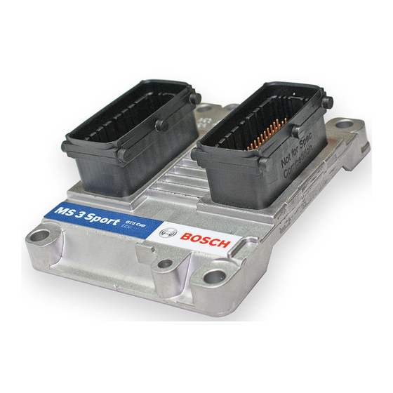
- Page 1 Engine Control Unit MS 3 Sport GT3 Cup Manual Version 1.2 17/04/2019...
-
Page 2: Table Of Contents
3 Technical Data ................................. Input channels ........................................Output channels........................................Power supply.......................................... Ignition trigger wheel ......................................Sensor recommendation ....................................4 Starting up the ECU ................................ Offline Data Application ....................................Online Data Application..................................... Activation of Software Options..................................5 Extensibility ..................................ii / 24 Engine_Control_Unit_MS_3_Sport_GT3_Cup_Manual Bosch Motorsport... -
Page 3: Getting Started
NOTICE The Bosch Motorsport MS 3 Sport GT3 Cup was developed for use by professionals and requires in depth knowledge of automobile technology and experience in motorsport. Us- ing the system does not come without its risks. -
Page 4: Sport Systems - Overview
2 | Sport Systems - Overview 2 Sport Systems - Overview The Sport Systems support an easy to understand user concept. The MS 3 Sport GT3 Cup is configured as an alpha/n version. This means that the engine characteristic map is based on engine speed, throttle position and engine temperature. -
Page 5: Technical Data
– pfuel (fuel pressure) – poil (oil pressure) Input channels for inductive speed sensors In the default configuration the MS 3 Sport GT3 Cup needs an inductive speed sensor on the ignition trigger wheel. Input channels for Hall-effect-speed sensors For the camshaft signal a Hall-effect sensor is necessary. Also for wheel speed measure- ment Hall-effect sensors are recommended. - Page 6 3 | Technical Data The MS 3 Sport GT3 Cup has integrated ignition power stages. The wiring is shown in the following picture. Illustration 2: Integrated ignition power stage NOTICE In case of ignition-caused malfunctions, please use screened sensor wires. A typical 6 cylinder engine with firing order 1-5-3-6-2-4 is connected as follows: Firing There are max.
-
Page 7: Power Supply
Firing 3.3 Power supply The MS 3 Sport GT3 Cup requires an external main relay to be wired to the harness. This relay is controlled by the MS 3 Sport GT3 Cup to realize that important information can be stored after switching off the ignition. -
Page 8: Ignition Trigger Wheel
Illustration 4: Power supply connection plan CAUTION Wrong polarity / high currents Wrong polarity of the terminals and high currents damage the MS 3 Sport GT3 Cup. Be careful to observe current limits of wires and connector pins! 3.4 Ignition trigger wheel To start the engine, the ECU requires information about the position of the camshaft and crankshaft. - Page 9 Modas Sport. The crankwheel trigger sensor must be an inductive type for default configuration. Bosch Motorsport recommends the use of in- ductive speed sensor IA-C. The picture below shows the correct installation position.
- Page 10 – The Hall-effect signal is the inversion of the shape of its cam trigger: the tooth effects a 'low' signal at the sensor and vice versa. – With 4 and 6 cylinder engines, the value of 66 degrees must be replaced by 78 de- grees. 10 / 24 Engine_Control_Unit_MS_3_Sport_GT3_Cup_Manual Bosch Motorsport...
-
Page 11: Sensor Recommendation
They offer good value for money. NOTICE The volume of applied sensors may differ depending on individual software extents. Detailed information about each sensor (technical specifications, characteristic curves, di- mension drawings, installation notes) can be found on our website www.bosch- motorsport.com. Model Range of application Connector Loom Part No. -
Page 12: Starting Up The Ecu
To work on these parameters after the first start-up, please refer the full-scope function sheet which is available in the “documentation” section of www.bosch-motorsport.com. CAUTION Serious engine damages using wrong setup data. - Page 13 To get a first estimation, the following characteristics must be known: – displacement per cylinder V – expected intake manifold pressure (after throttle) p [Pa] – desired lambda value λ – operating fuel pressure p [bar] Bosch Motorsport Engine_Control_Unit_MS_3_Sport_GT3_Cup_Manual 13 / 24...
- Page 14 TI_FAK Global factor, set to 1.0 for startup. TIBAT_OFF Battery voltage correction. Predefined value for Bosch Type valves EV6, characteristics can be requested by the valve manufacturer. TITAIR_FAK Correction by intake air temperature. This value is predefined. If unsure, set it to 1.0 con- stantly for first start up.
- Page 15 Base injection time for engine start. Can be set to a value near full load from the maps TI_MIN/DEF/MAX in atmospheric engines. Scale down proportional to boost pressure for turbo engines. Further corrections: Predefined. If unsure, set to 1.0 for first start up. Bosch Motorsport Engine_Control_Unit_MS_3_Sport_GT3_Cup_Manual 15 / 24...
- Page 16 This function corrects the injected fuel amount during changes of throttle position. It al- lows for additional fuel to be added immediately after the change in throttle position and then taper off over a number of engine cycles. 16 / 24 Engine_Control_Unit_MS_3_Sport_GT3_Cup_Manual Bosch Motorsport...
- Page 17 Further corrections: Predefined. If unsure, set to 0.0 for first startup. 4.1.5 Injection and Ignition Controls GEARCUT GCREV_THR Adjusts the engine torque reduction / blipper while shifting. Deactivate by setting = 32768. Bosch Motorsport Engine_Control_Unit_MS_3_Sport_GT3_Cup_Manual 17 / 24...
-
Page 18: Online Data Application
Check all sensors for errors (bits …_e) before starting the engine. Sensors and peripherals can be checked when the system is powered up electrically. NOTICE Do not start the engine before all steps in this chapter are carried out. 18 / 24 Engine_Control_Unit_MS_3_Sport_GT3_Cup_Manual Bosch Motorsport... - Page 19 Replacement value in case of error, should be in the normal temperature range of the en- gine (for example between 75 °C and 90 °C). TFUEL_x ; TOIL_x ; TEX_x ; TEX2_x ; TAIR_x If used: name as described in TMOT. Bosch Motorsport Engine_Control_Unit_MS_3_Sport_GT3_Cup_Manual 19 / 24...
- Page 20 Set to desired idle ATH value. ATH_CW Close throttle and set ATH_CW to 1. Open throttle fully and set ATH_CW to 2. Set throttle to idle point and set ATH_CW to 3. Check calibration by moving throttle. 20 / 24 Engine_Control_Unit_MS_3_Sport_GT3_Cup_Manual Bosch Motorsport...
-
Page 21: Activation Of Software Options
Starting up the ECU | 4 4.3 Activation of Software Options If you buy optional software, you will get a code number with eight ciphers from Bosch Motorsport. We enable this code number exclusively for one defined ECU serial number. It will work with this ECU only. -
Page 22: Extensibility
5 | Extensibility 5 Extensibility Bosch Motorsport developed a lot of extras for the ECUs. That is e.g.: – Displays – Data loggers – Telemetry units Find more information on: www.bosch-motorsport.com Moreover, you can expand some additional functions of your ECU by sending us the serial number. - Page 23 Bosch Motorsport Engine_Control_Unit_MS_3_Sport_GT3_Cup_Manual 23 / 24...
- Page 24 Bosch Engineering GmbH Motorsport Robert-Bosch-Allee 1 74232 Abstatt Germany www.bosch-motorsport.com...
Need help?
Do you have a question about the MS 3 Sport GT3 Cup and is the answer not in the manual?
Questions and answers