
Subscribe to Our Youtube Channel
Related Manuals for Vents VUT 180 P5


Summary of Contents for Vents VUT 180 P5
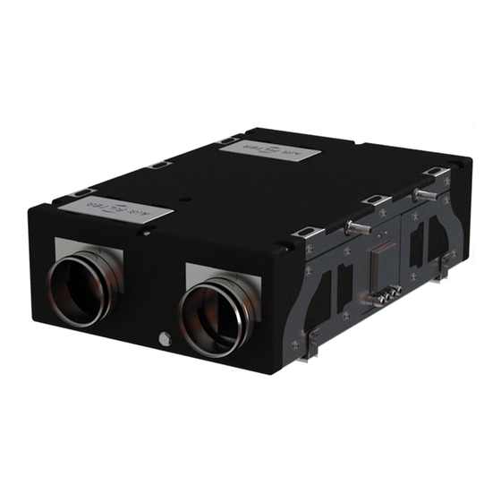
- Page 1 USER’S MANUAL VUT 180 P5 VUE 180 P5 VUT 180 P5 EC VUE 180 P5 EC VUT 180 P5B EC VUE 180 P5B EC Air handling unit...
-
Page 2: Table Of Contents
VUT/VUE 180 P5(B) (EC) CONTENTS Safety requirements ..................................2 Purpose ........................................ 4 Delivery set ......................................4 Designation key ....................................4 Technical data ....................................5 Unit design and operating principle ..........................6 Installation and set-up................................8 Connection to power mains ..............................12 Unit control ....................................... - Page 3 • Do not change the power cable length at your own discretion. Do not bend the power cable. Avoid damaging the power • Unpack the unit with care. cable. Do not put any foreign objects on the power cable. • Do not operate the unit outside the •...
-
Page 4: Purpose
VUT/VUE 180 P5(B) (EC) PURPOSE Due to the ability to save heating energy by means of energy recovery, the unit is an important element of energy-efficient premises. The unit is a component part and is not designed for stand-alone operation. The unit is designed to ensure mechanical air exchange in houses, offices, hotels, cafés, conference halls and other utility and public spaces as well as to recover the heat energy contained in the air extracted from the premises to warm up the filtered stream of supply air. -
Page 5: Technical Data
IP22 for the unit connected to the air ducts The unit design is constantly being improved, so some models may be slightly different from those ones described in this manual. TECHNICAL DATA MODEL VUT 180 P5(B) VUE 180 P5(B)* VUT 180 P5 VUE 180 P5*... - Page 6 VUT/VUE 180 P5(B) (EC) DESIGN AND OPERATING LOGIC The unit has the following operating logic: warm stale extract air from the room flows into the unit, where it is filtered by the extract filter, then air flows through the heat exchanger and is exhausted outside by the extract fan. Cold fresh air from the outside flows into the unit, where it is cleaned by the supply filter.
- Page 7 UNIT OPERATION MODES Heat recovery Warm extract air from the room flows into the unit and is cleaned in the extract filter. Then the air is moved through the heat exchanger and is exhausted outside with the extract fan. Cold fresh air from outside flows into the unit, where it is cleaned in the supply filter. Then the air flows through the heat exchanger and is directed to the room with the supply fan.
- Page 8 VUT/VUE 180 P5(B) (EC) MOUNTING AND SET-UP READ THE USER'S MANUAL BEFORE INSTALLING THE UNIT HV2 HUMIDITY SENSOR INSTALLATION AND CONNECTION The HV2 humidity sensor is not included in the delivery and can be ordered separately. Install the humidity sensor into the mount on the inner side of the unit and connect the humidity sensor to the appropriate connector. UNIT MOUNTING To attain the best performance of the unit and to minimise turbulence-induced air pressure losses connect the straight air duct section to the spigots on both sides of the unit while mounting.
- Page 9 Expansion Fastener anchor Mounting bracket Fasteners for mounting are not included in the delivery set and should be ordered separately. While choosing fasteners consider the material of the mounting surface as well as the weigh of the unit, refer to the Technical Data section.
- Page 10 Diagram 4. Wall vertical installation Diagram 5. Wall horizontal installation CONDENSATE DRAINAGE The VUT 180 P5(B) (EC) heat recovery units require condensate drainage. The hole for the drain pipes is in the cover of the unit. tooltip Remove the plug from the hole, open the service panel and install the drain pipe from the delivery set into the hole.
- Page 11 Plug Drain pipe Drain hole location in case of installation according to the Diagram 1 Then connect the drain pipe to the sewage system using the SG-32 U-trap kit (available upon separate order). The pipes are required to have a minimum slope of 3°. Each drain pipe is connected to a different U-trap. min 3°...
-
Page 12: Connection To Power Mains
VUT/VUE 180 P5(B) (EC) CONNECTION TO POWER MAINS DISCONNECT THE UNIT FROM POWER MAINS PRIOR TO ANY OPERATIONS. THE UNIT MUST BE CONNECTED TO POWER SUPPLY BY A QUALIFIED ELECTRICIAN. THE RATED ELECTRICAL PARAMETERS OF THE UNIT ARE GIVEN ON THE MANUFACTURER’S LABEL. - Page 13 External control units wiring diagram for units with an A2 control regulator Control regulator +10V 230 V/50-60 Hz +10V Name Wire** Control regulator 3 x 0.25 mm External control units wiring diagram for units with an External control units wiring diagram for units with an A40 A3/A4 control panel control panel L N PE T C1 C1 C2 C2 SL...
-
Page 14: Technical Maintenance
VUT/VUE 180 P5(B) (EC) TECHNICAL MAINTENANCE DISCONNECT THE UNIT FROM POWER SUPPLY BEFORE ANY MAINTENANCE OPERATIONS. FOLLOW THE SAFETY REGULATIONS WHEN CARRYING OUT MAINTENANCE. Maintenance operations of the unit are required 3-4 times per year. They include general cleaning of the unit and the following operations: 1. - Page 15 3. Fan maintenance (once per year). Even in case of regular maintenance of the filters, some dust may accumulate inside the fans and reduce the fan performance and supply air flow. Clean the fans with a soft cloth, brush, or using compressed air. Do not use water, aggressive solvents or sharp objects as they may damage the impeller.
-
Page 16: Storage And Transportation Regulations
VUT/VUE 180 P5(B) (EC) STORAGE AND TRANSPORTATION REGULATIONS • Store the unit in the manufacturer’s original packing box in a dry closed ventilated premise with temperature range from +5 °C to + 40 °C and relative humidity up to 70 %. •... -
Page 17: Manufacturer's Warranty
MANUFACTURER’S WARRANTY The product is in compliance with EU norms and standards on low voltage guidelines and electromagnetic compatibility. We hereby declare that the product complies with the provisions of Electromagnetic Council Directive 2014/30/EU, Low Voltage Directive 2014/35/ EU and CE-marking Directive 93/68/EEC. This certificate is issued following test carried out on samples of the product referred to above. The manufacturer hereby warrants normal operation of the unit for 24 months after the retail sale date provided the user's observance of the transportation, storage, installation, and operation regulations. - Page 18 VUT/VUE 180 P5(B) (EC) www.ventilation-system.com...
-
Page 19: Certificate Of Acceptance
CERTIFICATE OF ACCEPTANCE Unit Type Air handling unit Model VUT/VUE 180 P5___ EC A____ Serial Number Manufacture Date Quality Inspector’s Stamp SELLER INFORMATION Seller Address Phone Number E-mail Purchase Date This is to certify acceptance of the complete unit delivery with the user’s manual. The warranty terms are acknowledged and accepted. - Page 20 V170EN-03...
Need help?
Do you have a question about the VUT 180 P5 and is the answer not in the manual?
Questions and answers