Advertisement
Quick Links
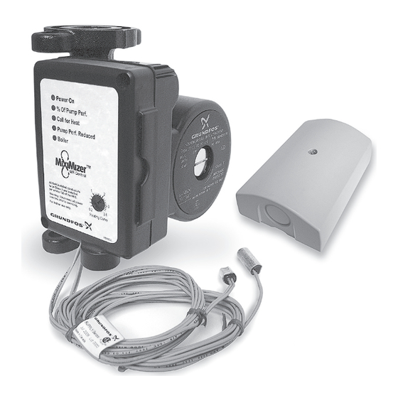
GRUNDFOS INSTRUCTIONS
Grundfos MixiMizer
Installation and Operation
1.
Shipment
Inspection
2.
General
MixiMizer
Features
3.
Pump
Installation
4.
Sensor
Installation
Pumps Incorporating the
(MR) Mixing Reset Control
with Date Code 0718 or higher
5.
Settings
6.
Start Up
7.
Error Messages
& Trouble Shooting
8.
MixiMizer
Technical Data
™
Advertisement

Related Manuals for Grundfos MixiMizer


Summary of Contents for Grundfos MixiMizer
- Page 1 GRUNDFOS INSTRUCTIONS Grundfos MixiMizer ™ Installation and Operation Pumps Incorporating the (MR) Mixing Reset Control with Date Code 0718 or higher Shipment Settings Inspection General Start Up MixiMizer Features Pump Error Messages & Trouble Shooting Installation Sensor MixiMizer Installation Technical Data...
-
Page 2: Shipment Inspection
The hot water heating system can now be accurately and comfortably controlled by modulating the hot water supply. As the outdoor temperature changes, the MixiMizer will automatically calculate the pump speed required, to ensure proper water temperature for your heating system. - Page 3 When installing and using this electrical equipment, basic safety precautions and local code requirements should always be followed, including the following: CAUTION: The installer must ensure that this control and its wiring are isolated and/or shielded from strong sources of electromagnetic noise.
- Page 4 General MixiMizer Features • All minimum and maximum settings are operating, not safety limits. Necessary auxiliary equipment and safety devices must be added. • The boiler return minimum temperature is fixed at 135°F. This function can be disabled by a DIP switch.
-
Page 5: Pump Installation
Optional Zone Control Input: The unit can • accept external “Call For Heat” input signal. This must be a powered signal (20 to 30 V AC .1 VA). This function can be enabled by a DIP switch. Warm Weather Shut Down (WWSD): When the •... - Page 6 Note 1: The injection piping (Supply and Return) must be at least one pipe diameter smaller than the piping of the boiler and system loops. Note 2: There must be a maximum of 4 pipe diameters between the tees in the boiler and system loops in order to prevent ghosts flow when the variable speed injection pump is off and either the boiler pump or system pump is on.
- Page 7 Arrows on the side or bottom of the pump chamber indicate direction of flow through the pump. Grundfos Miximizer pumps can be installed in both vertical and horizontal lines. Flow direction should be from the boiler loop into the system loop.
- Page 8 If the terminal box position needs to be changed, ensure that the electrical supply is turned off and close the isolation valves before removing the Allen screws. To change control box position: • Remove the four (4) Allen screws (4 or 5mm wrench) while supporting the stator (motor).
- Page 9 Outdoor Air Temperature Sensor (OATS): The Outdoor Air Temperature Sensor includes a built in 10 kW (ohm) thermistor which provides an accurate measurement of the outdoor temperature. The OATS sensor is protected by a white U.V. resistant PVC plastic enclosure (Fig. 3A & 3B). Sensor Figure 3B - Open Outdoor Air Temperature Sensor...
- Page 10 Sensor with rear Sensor mounted Sensor with bottom entry wiring onto 2" x 4" electrical entry wiring box. Figure 4 - Mounting the Outdoor Air Temperature Sensor (OATS) • The OATS should be installed at an elevation above the ground that will prevent accidental dam- age or tampering.
- Page 11 • The sensor should be placed downstream of a pump or after an elbow or similar fitting. This is especially important if large diameter pipes are used as the thermal stratification within the pipe can result in erroneous sensor readings. Proper sensor location requires that the fluid is thoroughly mixed within the pipe before it reaches the sensor.
- Page 12 Fig. 8 Boil Optional Boiler On/Off Boil Output Os / V Outside Temp Sensor Ret / I Com(-) Return Sensor Supply Sensor Class 2 Optional Zone Only Control Input Settings Dip switch settings: ⇑ Figure 9 - Dip Switches POSITION SWITCH DEFAULT Permanent...
- Page 13 Heating Curve - Dial Set Point: Before adjusting the dial settings, read through the sequence of operation to ensure that you understand how this control operates. The Heating Curve setting deter- mines the number of degrees the supply water temperature is raised for each one degree drop in outdoor temperature.
- Page 14 Table 2 Heating Curve 3.6 3.0 > WWSD Table 3 Page 13...
- Page 15 Start Up DO NOT START THE PUMP UNTIL THE SYSTEM • HAS BEEN FILLED, FLUSHED, PROPERLY vENTED, AND CHECKED FOR LEAKS. • Ensure that water does not enter the terminal box during the installation process. • Do not use the pump to vent the system. Install additional ventilation for system purging.
-
Page 16: Error Messages And Troubleshooting
Error Messages and Trouble Shooting Whenever a fault is detected in any of the sensors, the control LEDs will flash in a specific way, to indicate the lo- cation of the problem, and the control will assume a specific operating condition. •... - Page 17 • Call For Heat and Pump Performance Reduced LEDs are flashing (Fig. 14): – There is a short or open circuit to Boiler Return Sensor – Boiler protection is disabled Power On % Of Pump Perf. Call for Heat Pump Perf. Reduced Boiler Figure 14 - Control Lights (PPR &...
- Page 18 OATS / Return / Supply Temperature Resistance Chart Table 4 Temperature Resistance Temperature Resistance � � 490,813 46,218 405,710 7,334 336,606 5,828 280,279 5,210 234,196 4,665 196,358 4,184 165,180 3,760 139,402 3,383 118,018 3,050 100,221 2,754 85,362 2,490 72,918 2,255 62,465 2,045 53,658...
- Page 19 MixiMizer Technical Data Maximum Ambient Temperature: • 107°F (42°C) with Control Box vertical • 105°F (41°C) with Control Box on top of pump and horizontal Outdoor Air Temperature Sensor: Approvals: CSA, UL Terminals: Out/V & Com (-) 5V DC +/- 5% Max 0.166 mA DC +/- 5% Max...
- Page 20 UP15 Pump: Max Working Pressure: 145 PSI Min. Inlet Pressure: 5 PSI Approvals: UL, cUL listed Integrated Check Valve: Yes UP15-42FC/MR: Connection: GF 15/26 Flange - (2) 1/2” Diam. Bolt Holes Flow Range (GPM): 0 - 9 Head Range (ft.): 0 - 14 Motor: 2 Pole, Single Phase Amps:...
-
Page 21: Limited Warranty
Limited Warranty Products manufactured by GRUNDFOS PUMPS CORPORATION (GRUNDFOS) are warranted to the original user only to be free of defects in material and workmanship for a period of 24 months from date of installation, but not more than 30 months from date of manufacture.
Need help?
Do you have a question about the MixiMizer and is the answer not in the manual?
Questions and answers