Sign In
Upload
Download
Table of Contents
Contents
Add to my manuals
Delete from my manuals
Share
URL of this page:
HTML Link:
Bookmark this page
Add
Manual will be automatically added to "My Manuals"
Print this page
×
Bookmark added
×
Added to my manuals
Manuals
Brands
Check Point Manuals
Server
Smart-1 25
Getting started manual
Check Point Smart-1 25 Getting Started Manual
Hide thumbs
1
2
3
4
5
Table Of Contents
6
7
8
9
10
11
12
13
14
15
16
17
18
19
20
21
22
23
24
25
26
27
28
29
30
31
32
33
34
35
36
37
38
39
40
41
page
of
41
Go
/
41
Contents
Table of Contents
Bookmarks
Table of Contents
Important Information
Health and Safety Information
Table of Contents
Introduction
Welcome
Smart-1 Overview
Security Management Software Blades
Smartevent
This Document Provides
Shipping Carton Contents
Terminology
Smartevent Terminology
Mounting Smart-1 25 in a Rack
Safety Instructions
Determining Space and Weight Requirements
Rack Mounting Hardware and Required Tools
Preparing the Appliance
Attaching the Appliance Rails to the Appliance
Attaching the Appliance Ear Brackets (Optional)
Attaching the Mounting Brackets to the Slide
Attaching the Slide and Mounting Bracket Assembly to the Rack
Installing Smart-1 25 in the Rack
Configuring Smart-1
Connecting the Power Cables and Power on
Using the First Time Configuration Wizard
Starting the First Time Configuration Wizard
Welcome
Appliance Date and Time Setup
Network Connections
Routing Table
DNS and Domain Settings
Security Management Installation Type
Security Management
Smartevent and Smartreporter Suite Installation Type
Web/Ssh and GUI Clients Configuration
Secure Internal Communication
Download Smartconsole Applications
Summary
Installing the Smartconsole GUI Clients
Completing the Configuration
Advanced Configuration
Connecting to the Smart-1 CLI
Configuring Smartevent
Preparing Smartevent on Security Management Server
Configuring the Smartevent Clients
Defining the Internal Network for Smartevent
Defining Correlation Units and Log Servers for Smartevent
Creating a Consolidation Session for Smartreporter
Smart-1 Hardware
Smart-1 5
Front Panel
LCD Display Screen
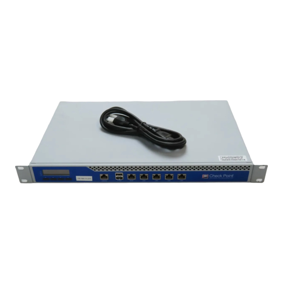
Smart-1 25
Front Panel
LCD Display Screen
Hard Disk Drives
Customer Replaceable Parts
Power Supply
Hard Disk Drives
Removing a Hard Disk Drive
Installing a Hard Disk Drive
Restoring Factory Defaults
Restoring Factory Defaults Using the Webui
Restoring Factory Defaults Using the Console
Restoring Using the LCD Panel
Lights out Management
Introduction
Initial Login
Basic Configuration Options
Remotely Controlling the Appliance
Remotely Controlling the Power of the Appliance
Managing LOM Card Users
Configuring LOM Keyboard and Mouse
Configuring LOM Network
Setting the Date and Time
Defining a LOM Login Message
Registration and Support
Registration
Support
Where to from here
Advertisement
Quick Links
1
Smart-1 Overview
2
Connecting the Power Cables and Power on
3
Smart-1 Hardware
Download this manual
Smart-1 5 & Smart-1 25
Getting Started Guide
Models: S-10, S-21
8 December 2011
704548
Table of
Contents
Previous
Page
Next
Page
1
2
3
4
5
Advertisement
Table of Contents
Need help?
Do you have a question about the Smart-1 25 and is the answer not in the manual?
Ask a question
Questions and answers
Related Manuals for Check Point Smart-1 25
Server Check Point Smart-1 50 Getting Started Manual
Security management platform, s-30; s-40 (45 pages)
Server Check Point Smart-1 150 Installtion Manual
Installing hard disk drives (4 pages)
Server Check Point Smart-1 5 Getting Started Manual
(41 pages)
Server Check Point QUANTUM SMART-1 6000-L Replacement Manual
Replacing storage devices (12 pages)
Server Check Point Integrity Advanced Server Installation Manual
Advanced server (53 pages)
Server Check Point 21400 Platform Installation Instructions Manual
Slide rail installation (10 pages)
Server Check Point 21000 Replacing
Replacing appliances cooling fan units (3 pages)
This manual is also suitable for:
Smart-1 5
S-21
S-10
Table of Contents
Print
Rename the bookmark
Delete bookmark?
Delete from my manuals?
Login
Sign In
OR
Sign in with Facebook
Sign in with Google
Upload manual
Upload from disk
Upload from URL


Need help?
Do you have a question about the Smart-1 25 and is the answer not in the manual?
Questions and answers