Table of Contents
Advertisement
Quick Links
Advertisement
Table of Contents

Related Manuals for Check Point Smart-1 50


Summary of Contents for Check Point Smart-1 50
-
Page 1: Getting Started Guide
Smart-1 50/150 Getting Started Guide Models: S-30, S-40 23 February 2011... - Page 2 Check Point. While every precaution has been taken in the preparation of this book, Check Point assumes no responsibility for errors or omissions. This publication and features described herein are subject to change without notice.
-
Page 3: Important Information
First Time Configuration Wizard" on page 19) 26 august 2010 First release of the document Feedback Check Point is engaged in a continuous effort to improve its documentation. Please help us by sending your comments (mailto:cp_techpub_feedback@checkpoint.com?subject=Feedback on Smart-1 50/150 Getting Started Guide). -
Page 4: Health And Safety Information
Welcome Health and Safety Information Read the following warnings before setting up or using the appliance. Warning - Do not block air vents. A minimum 1/2-inch clearance is required. Warning - This appliance does not contain any user-serviceable parts. Do not remove any covers or attempt to gain access to the inside of the product. - Page 5 Welcome Federal Communications Commission (FCC) Statement: Note: This equipment has been tested and found to comply with the limits for a Class A digital device, pursuant to Part 15 of the FCC Rules. These limits are designed to provide reasonable protection against harmful interference when the equipment is operated in a commercial environment.
-
Page 6: Table Of Contents
Shipping Carton Contents..................9 Terminology......................9 SmartEvent Terminology ................10 Multi-Domain Security Management/Provider-1 Terminology ......10 Rack Mounting Smart-1 50/150 ................12 Safety Instructions ....................12 Determining Space and Weight Requirements ...........12 Rack Mounting Hardware and Tools ..............13 Disconnecting the Appliance Rail from the Mounting Bracket ......14 Attaching the Appliance Rails to the Appliance ...........15... - Page 7 Restoring Factory Defaults .................. 38 Restoring Factory Defaults using the WebUI ............38 Restoring Factory Defaults using the Console ............38 Restoring Using the LCD Panel ................39 Lights Out Management ..................41 Introduction ......................41 Initial Login ......................41 Basic Configuration Options ................42 Remotely Controlling the Appliance ..............42 Remotely Controlling the Power of the Appliance ..........42 Managing LOM Card Users ................43 Configuring LOM Keyboard/mouse Settings ............43...
-
Page 8: Introduction
Terminology Welcome Thank you for choosing Check Point’s Smart-1. We hope that you will be satisfied with this solution and our support services. Check Point products provide your business with the most up to date and secure solutions available today. -
Page 9: Security Management Software Blades
Shipping Carton Contents Item Description Appliance A single Smart-1 appliance Rack Mounting Accessories Hardware mounting kit 2 power cables (Smart-1 50) Cables 3 power cables (Smart-1 150) 1 standard LAN cable 1 serial console cable User license agreement Documentation ... -
Page 10: Smartevent Terminology
Terminology Security Management server: The server used by the system administrator to manage the security policy. The organization’s databases and security policies are stored on the Security Management server and downloaded to the gateway. Smart-1 is a Security Management server. ... - Page 11 Terminology Name Before R75 Name Starting with R75 (Used in this Guide) Multi-domain server (MDS) Multi-Domain Server Customer Domain Customer Management Add-on (CMA) Domain Management Server Customer Log Module (CLM) Domain Log Server Multi-Domain Log Module (MLM) Multi-Domain Log Server Introduction Page 11...
-
Page 12: Rack Mounting Smart-1 50/150
Chapter 2 Rack Mounting Smart-1 50/150 These instructions show how to install Smart-1 50 and 150 in a standard 19 inch rack. In This Chapter Safety Instructions Determining Space and Weight Requirements Rack Mounting Hardware and Tools Disconnecting the Appliance Rail from the Mounting Bracket... -
Page 13: Rack Mounting Hardware And Tools
Rack Mounting Hardware and Tools Important - The Smart-1 appliance is very heavy. To lift and install it: Two people are required for Smart-1 50. Three people are required for Smart-1 150. The distance from the center of any hole to the center of the third hole above it is equivalent to 1U. -
Page 14: Disconnecting The Appliance Rail From The Mounting Bracket
Screws for Smart-1 150 Secures the appliance rail to Smart-1 150 #6-32*6 Appliance bracket ear for Smart-1 Attaches to the Smart-1 50 front panel. Both bracket ears are identical. Screw for Smart-1 50 appliance Attaches the Smart-1 50 bracket ears to the... -
Page 15: Attaching The Appliance Rails To The Appliance
Attaching the Appliance Rails to the Appliance Attach the Appliance Rails to the Appliance. Use the same appliance rails for Smart-1 50 and for Smart-1 150. You don't need to do this in the server room. 1. Identify the front of an appliance rail. One end of the rail is marked with FRONT. -
Page 16: Attaching The Mounting Brackets To The Rack
You don't need to be in the server room to attach the appliance handles or ear brackets to the appliance. To connect the appliance bracket ears or handles to the front of the appliance: 1. Attach the appliance ear bracket to one side of the appliance. For Smart-1 50 use three screws. For Smart-1 150 use two screws. -
Page 17: Installing Smart 1 50/150 In The Rack
7. Repeat for the other side of the rack: Attach the mounting bracket to the other side of the rack. Installing Smart 1 50/150 In the Rack Carefully install the Smart-1 50/150 in the rack. Important - The Smart-1 appliance is very heavy. To lift and install it: ... - Page 18 1. Line up the appliance rail on the appliance with the mounting bracket rails. 2. Carefully slide the appliance into the mounting bracket rails. 3. Push the appliance in until the appliance locks in the rails. Rack Mounting Smart-1 50/150 Page 18...
-
Page 19: Configuring Smart-1
Chapter 3 Configuring Smart-1 The basic workflow for configuring Smart-1 is: 1. Connect the cables and power on. 2. Perform the initial configuration using the First Time Configuration Wizard. 3. Install the SmartConsole GUI clients. In This Chapter Connecting the Power Cables and Power On Using the First Time Configuration Wizard Installing the SmartConsole GUI Clients Advanced Configuration... -
Page 20: Welcome
Using the First Time Configuration Wizard The management interface is marked Mgmt. This interface is preconfigured with the IP address 192.168.1.1. 2. Connect to the management interface by connecting from a computer on the same network subnet as the management interface (for example, with IP address 192.168.1.x and netmask 255.255.255.0). This can be changed later through the management interface. -
Page 21: Network Connections
Using the First Time Configuration Wizard Network Connections Configure Network Connections in the Network Connections page. You may modify the Mgmt IP address and connectivity will be preserved. A secondary interface is created automatically to preserve connectivity. This interface can be removed after the wizard is completed in the Network >... -
Page 22: Security Management
Secondary Security Management is the Security Management server that takes over if the Primary Security Management server fails. This option applies only in a Management HA deployment. Log Server is the repository for log entries generated on gateways. Check Point gateways send their log entries to the Log Server. Configuring Smart-1... - Page 23 SmartConsole Applications window, you can download SmartConsole and install it on Windows machines. For a detailed list of supported Windows operating systems for SmartConsole refer to the release notes of your Check Point version in the Check Point Support Center (http://supportcenter.checkpoint.com). Summary The Summary page appears.
-
Page 24: Multi-Domain Security Management Settings
Using the First Time Configuration Wizard Multi-Domain Security Management Settings The First Time Configuration Wizard screens in this section apply to a Smart-1 with a Multi-Domain Security Management image. Note - This section uses terminology introduced in R75 ("Multi-Domain Security Management/Provider-1 Terminology"... -
Page 25: Installing The Smartconsole Gui Clients
SmartConsole Applications window, you can download SmartConsole and install it on Windows machines. For a detailed list of supported Windows operating systems for SmartConsole refer to the release notes of your Check Point version in the Check Point Support Center (http://supportcenter.checkpoint.com). Summary The Summary page appears. -
Page 26: Advanced Configuration
Advanced Configuration 4. If Multi-Domain Security Management is deployed, follow the same procedure to download the SmartDomain Manager. You have now completed the Smart-1 configuration. To start working with your Smart-1 appliance as a Security Management Server refer to the Security Management Server Administration Guide. - Page 27 Migration from Existing Provider-1 Machines # $MDS_SYSTEM/install/mds_import.sh <full path to the imported configuration> 4. Start the mds. Note that the first start-up of the mds after import takes considerably longer than subsequent start-ups. Configuring Smart-1 Page 27...
-
Page 28: Configuring Smartevent
2. In SmartDashboard, create a new host for each computer that contains a component of SmartEvent: a) Select Manage > Network Object > New > Check Point > Host b) In the General Properties window, click Communication and enter the activation key. -
Page 29: Enabling Connectivity With Multi-Domain Security Management
2. In SmartDashboard, create a new host for each computer that contains a component of SmartEvent: a) Select Manage > Network Object > New > Check Point > Host b) In the General Properties window, click Communication and enter the activation key. -
Page 30: Defining Correlation Units And Log Servers For Smartevent
The report data will be stored in the default database table named CONNECTIONS. The preselected logs are the sequence of log files that are generated by Check Point products. The preselected logs session will begin at the beginning of the last file in the sequence, or at the point the sequence was stopped. -
Page 31: Smart-1 Hardware
Chapter 5 Smart-1 Hardware This chapter provides instructions for installing and removing hardware components on the Smart-1 appliance. In This Chapter Smart-1 50 Front Panel Smart-1 150 Front panel LCD Display Screen Customer Replaceable Parts Page 31... -
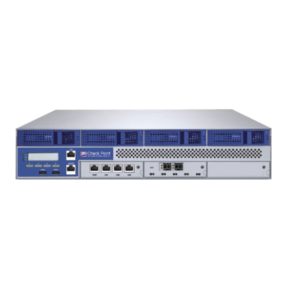
Page 32: Smart-1 50 Front Panel
Smart-1 50 Front Panel Smart-1 50 Front Panel Description LCD display screen Screen operation keys USB ports Console port - for a serial connection to the appliance using a terminal emulation program such as HyperTerminal LOM (Lights-out Management) port Management configuration port Built-in ethernet ports (Lan1-Lan3) slot for optional fiber channel SAN card. -
Page 33: Smart-1 150 Front Panel
Smart-1 appliances (other than Smart-1 25) have an LCD screen that can be used to perform basic management operations. The management IP address, netmask and default gateway of the Check Point appliance can be configured. The appliance can also be rebooted and shut down. -
Page 34: Customer Replaceable Parts
Up to twelve hard disk drives Three cooling fans Unless directed to do so by Check Point technical support, customers are prohibited by warranty and support agreements from replacing any parts. Customers are prohibited from opening the Smart-1 case under any circumstances. -
Page 35: Hard Disk Drives
3. Insert the power cord. Hard Disk Drives Smart-1 50 contains 4 hot-swappable redundant hard disk drives (RAID 10). Smart-1 150 can contain up to 12 hot-swappable hard disk drives. Implemented by a dedicated LSI Logic RAID controller, Smart-1 performs RAID10 mirroring and striping across all of the installed hard disk drives. -
Page 36: Removing A Hard Drive
The hard disk drives are numbered 1-4 on Smart-1 50 from left to right, and 1-12 on Smart-1 150 from left to right, top to bottom. The upper left hard drive is #1, upper right hard drive is #4. On Smart-1 150 the lower right hard drive is #12. -
Page 37: Cooling Fans
5. Make sure that the additional hard drives have been inserted correctly and are recognized by the system by running the command /sbin/raidconfig status 6. Stop all Check Point processes by running cpstop or mdsstop 7. Stop all other processes that are using /var/log. To see a list of these processes, run lsof /var/log 8. -
Page 38: Restoring Factory Defaults
Restoring Factory Defaults using the WebUI Smart-1 contains a default factory image for Security Management server or Multi-Domain Security Management according to the Check Point license you have purchased. Choose the image that is applicable to your license. To revert to an earlier image, in the Smart-1 WebUI: 1. -
Page 39: Restoring Using The Lcd Panel
Restoring Using the LCD Panel Restoring Using the LCD Panel To restore the Smart-1 appliance to its default factory configuration using the LCD Panel keys: 1. Reboot or power on the appliance. 2. When the countdown begins, press any of the arrow keys. The Boot menu appears. - Page 40 Restoring Using the LCD Panel When the appliance has been restored to its default factory configuration, the appliance reboots and the Initializing message appears. Restoring Factory Defaults Page 40...
-
Page 41: Lights Out Management
Chapter 7 Lights Out Management This chapter discusses the Lights-Out Management (LOM) integrated card that is supplied with the Smart-1 50/150 appliance and basic configuration options. In This Chapter Introduction Initial Login Basic Configuration Options Remotely Controlling the Appliance Remotely Controlling the Power of the Appliance Managing LOM Card Users Configuring LOM Keyboard/mouse Settings Configuring LOM Settings... -
Page 42: Basic Configuration Options
Basic Configuration Options Basic Configuration Options The options in the main menu on the LOM home page enable you to access the following basic configuration options: Remotely control the appliance Remotely control the power of the appliance Manage LOM card users ... -
Page 43: Managing Lom Card Users
Managing LOM Card Users Managing LOM Card Users You can create, modify, and delete users. You can also assign privileges to users. To create a user: 1. Click the LOM User Management menu option. The User Management page appears. 2. Select a row and click Create. The User Add dialog box appears. 3. -
Page 44: Configuring Lom Settings
Configuring LOM Settings Relative (for Linux) 3. Click Apply Changes. Configuring LOM Settings The network settings option enables you to change the default IP address and other basic network settings of the LOM card. To configure LOM network settings: 1. -
Page 45: Registration And Support
See the relevant documentation for your software version on the Check Point Support Center: Check Point documentation is available on the Check Point Support Center (http://supportcenter.checkpoint.com). Be sure to also use the Online Help when you are working with the Check Point SmartConsole clients. Page 45...
Need help?
Do you have a question about the Smart-1 50 and is the answer not in the manual?
Questions and answers